Nuke Collaboration Unit
Second project of the course, concentrating on further basic techniques of the postprocess and placing the information within the context of practical examples and exercises.
All pictures can be enlarged by clicking on them.
Week 1
Clean up – Prep and paint, removal, colour match
First stage of every compositing job, mostly done by most junior position part of the team, Matchmove and/or Prep and Paint artists.
The idea of this stage is to clean the plate and prepare it for the further work that is supposed to be done on it in further stages.
Denoise/ Degrain and Removal
The first step in every comp should be denoise, which removes the grain from the footage which, at the end of the work, is added again to keep the footage looking authentic and realistic (without grain it looks artificial).
Further the elements that are not desired in the final outcome are removed (second picture).
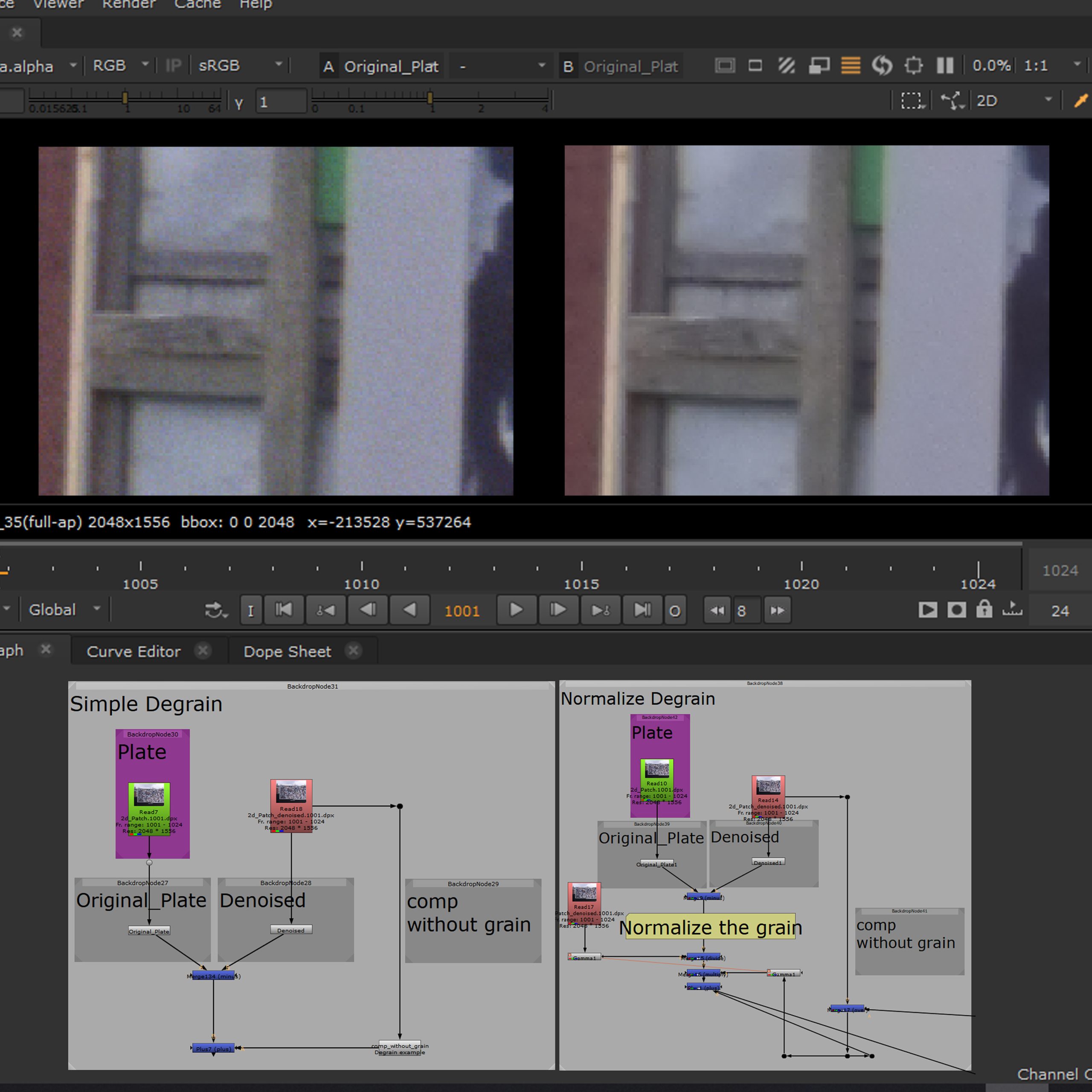
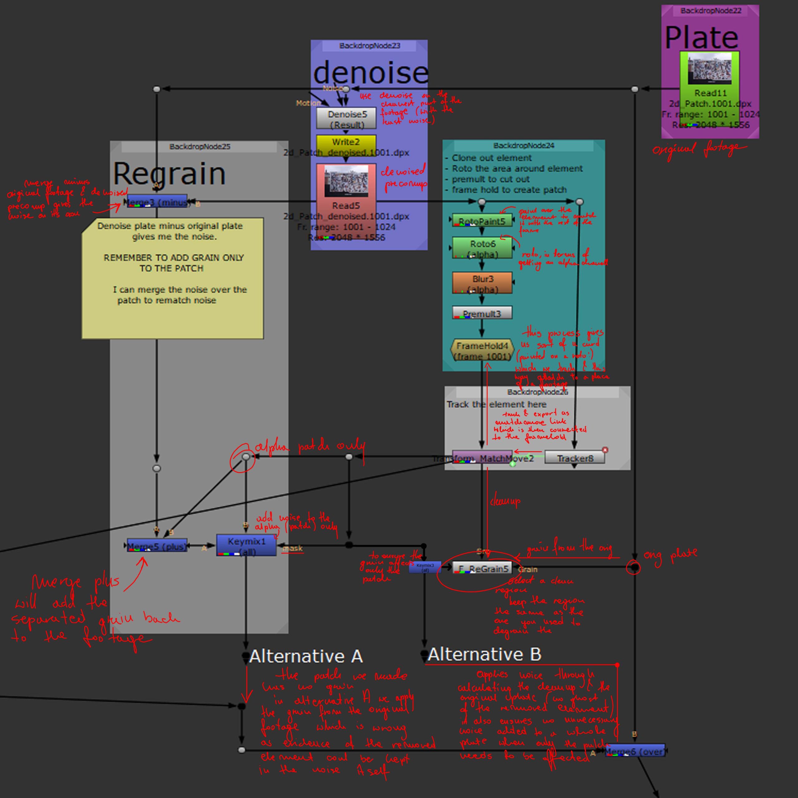
The second screenshot goes into the details of a process demonstrating how degrain works in practice. The footage was denoised after which some elements were removed through creating a 2D patch with an alpha created through tracked roto.
If we merge minus the original footage with the denoised one we can store and later reuse the original noise that we plug into the cleaned up footage through merge plus operation, this however adds additional grain to the whole footage not only the patch that we have created, to avoid that we can use a keymix through which we will add the grain to alpha only (the patch). alternatively we can use a keymix (to apply only to alpha) together with a FReGrain node (src to the cleaned up version and grain to the original footage).
To check merge difference the result of the clean up and the original footage (grain should show only on the patch). Further checks and issues depicted in the images below (all based on previously mentioned re graining of the patch created).
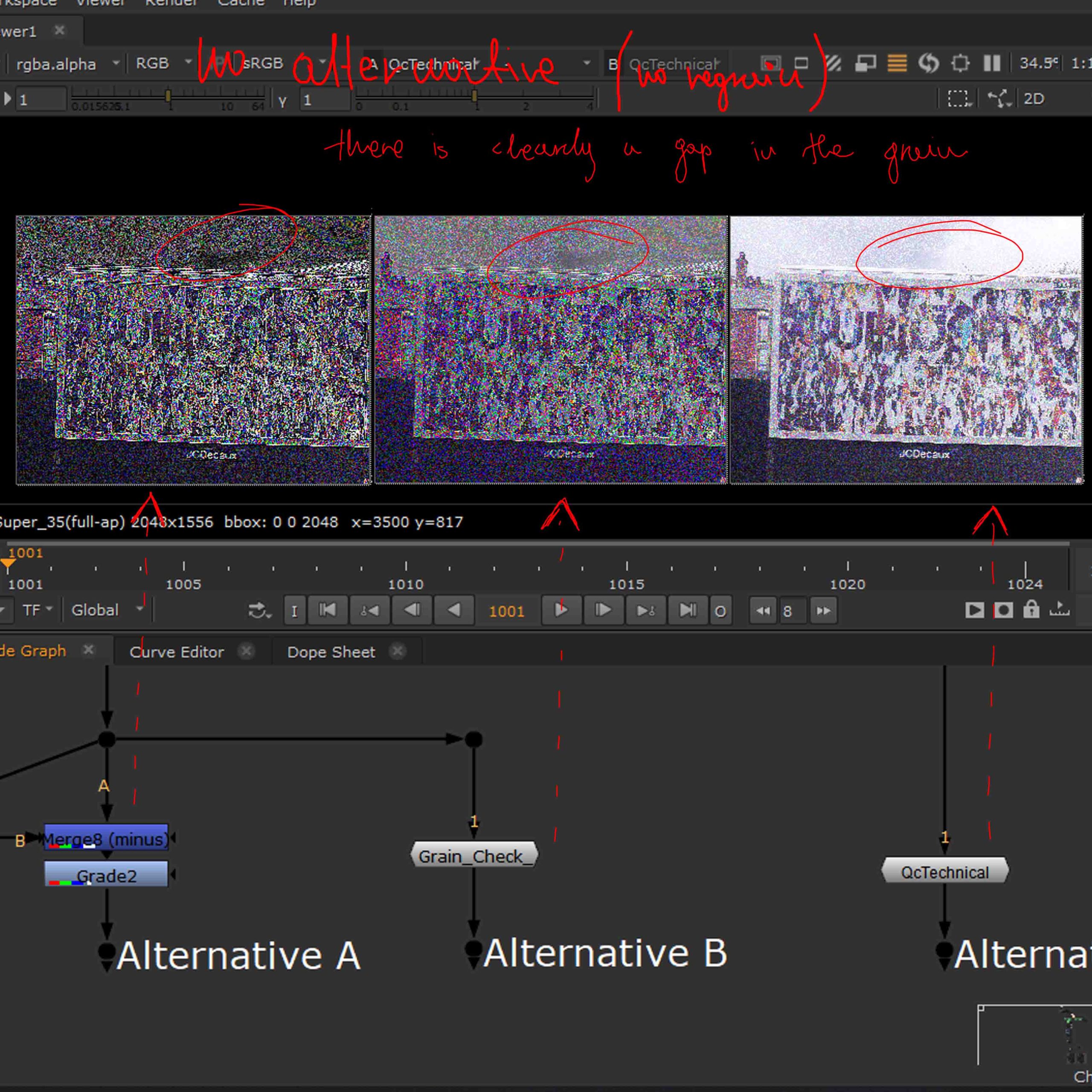
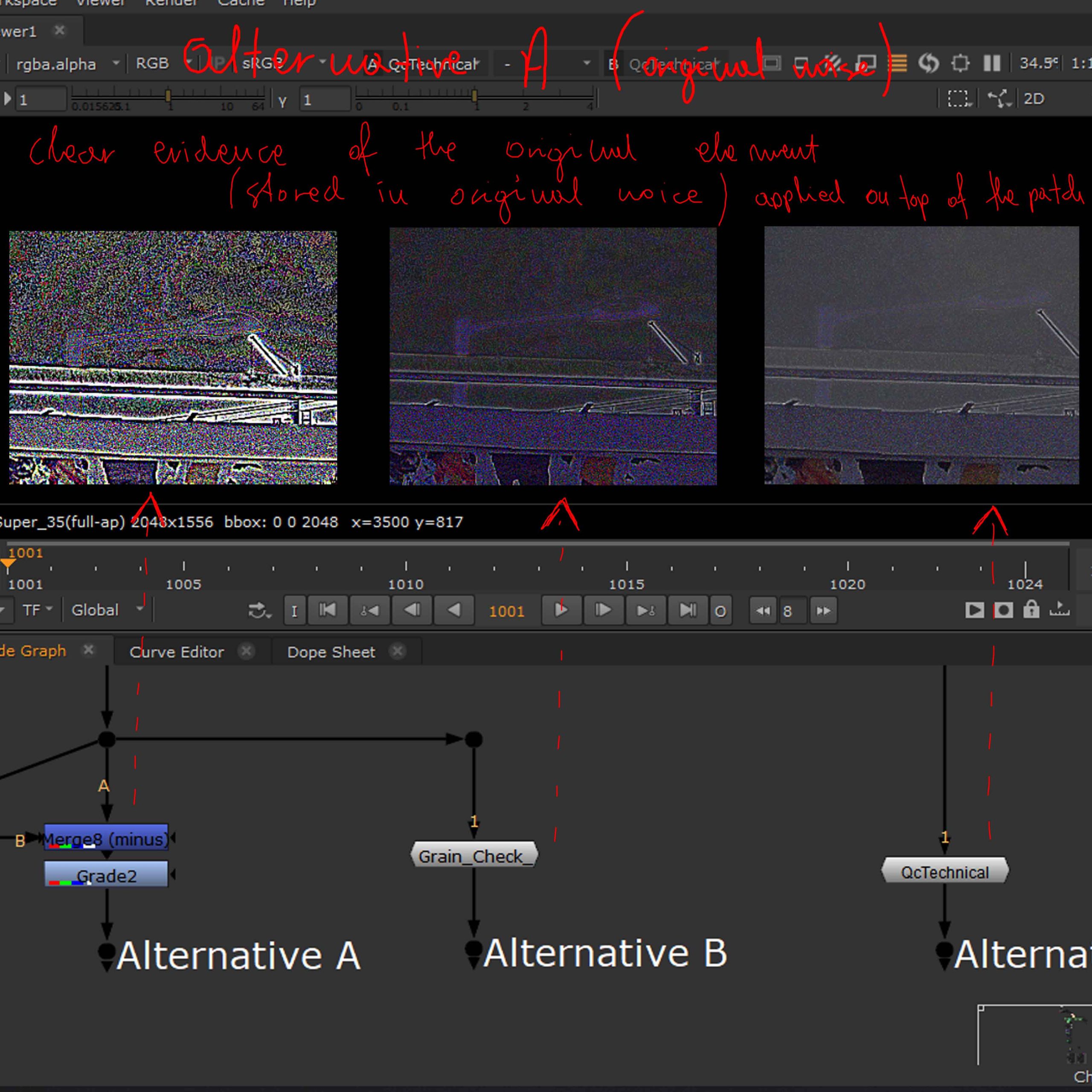

First picture shows a clear gap in the grain where we placed the patch, this happened due to not regraining the patch at all. The second picture shows a ghost of the element we had previously removed as we had used the grain from the original footage and finally the third one is the correct regrain, in which no ghost of the element remains and the grain is clearly present and matching the original footage.
Marker Removal and Colour matching intro
Removing tracking markers from the footage after they have been used.
Most often done with the use or a RotoPaint node which allows cloning of the surrounding areas to match the colour of the face on the created patch (supplies alpha that is essentially tracked and placed on top of the footage to cover the desired area).

A shortcut ending in a completely in admissive outcome in which the patch is clearly visible in frames other that it was painted on.
To start with the work is done on a footage that has not been denoised and with the use of a wrong reference frame. The patch is a dot of colour that does not interact with the rest of the area in anyway making it visible when there is a change in lighting on the footage.

Colour matching is based on taking colours from one image and applying them to another in terms of changing the original colour of one of them and making it appear as their colour schemes match and they belong in the same world.
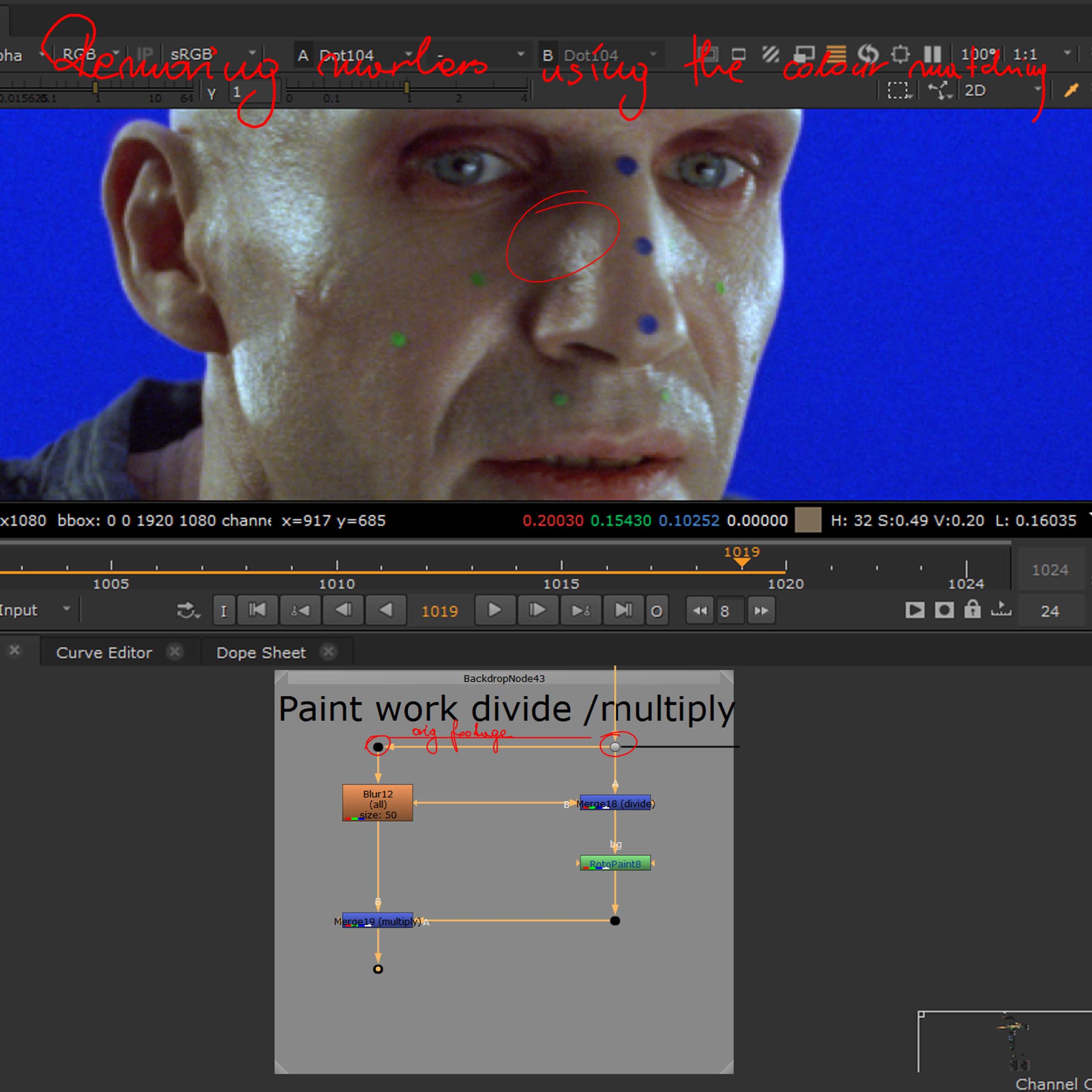
The first picture shows the basic process which is employed in matching two images (reformat, to match size, blur to loose the details and keep the colours instead and merge to apply the colour to another image).
The second picture employs the technique of colour matching in the general process of removing tracking markers from face, which achieves a significantly better result than the first discussed method.
The idea is to use the original footage that has been blurred and merge dive it with the original (no blur) one, then roto the marker and merge multiply with the blurred version in terms of getting an estimated colour value that should be in that area, and since we are working with footage (both orig. and blurred), the changing light information is still going to be present, resulting in an interactive patch that matches relatively well.
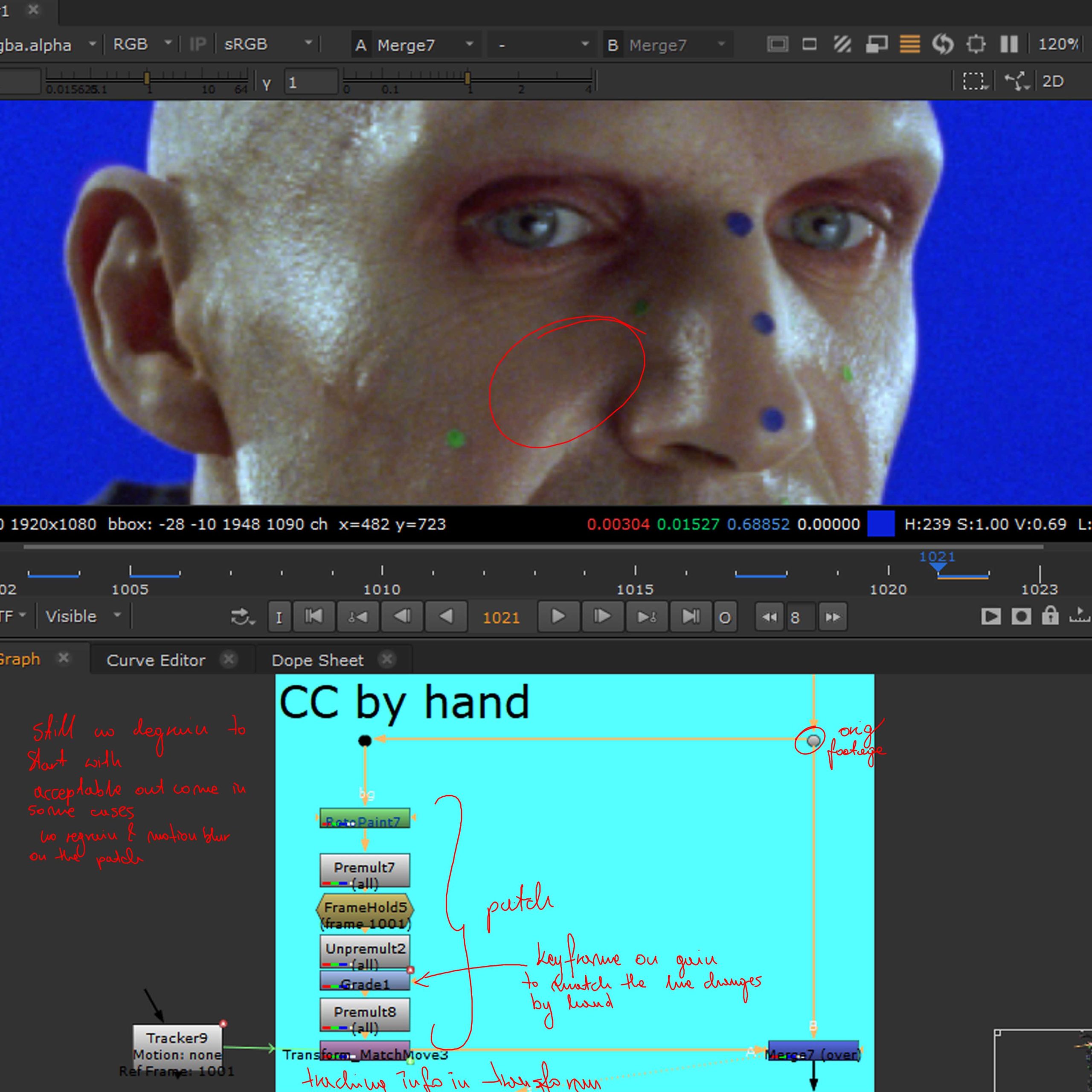

The first picture depicts the process of Colour Correction by hand which centres around creating a patch and hand grading it depending on the requirement and original footage change (keyframe grade on patch).
And finally Interactive Light Patch process, creates a patch that takes its colour from an instance of the footage which we transform a tiny bit (so it doesn’t calculate the original area with the marker colour).
Week 2
Clean up II
Luminance adjustement
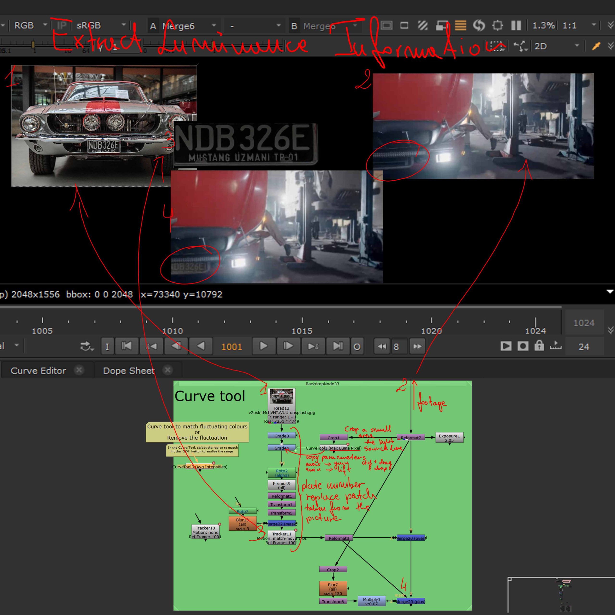
The curve tool allows the extraction of luminance information from footage which allows for easy application of the same luminance to another footage or image, in this case the lights from the car are applied to a changed licence plate to make the whole image look like one piece.
This is useful when the lighting information of a footage is changing and another part (or a new part as in this case) needs to match it.
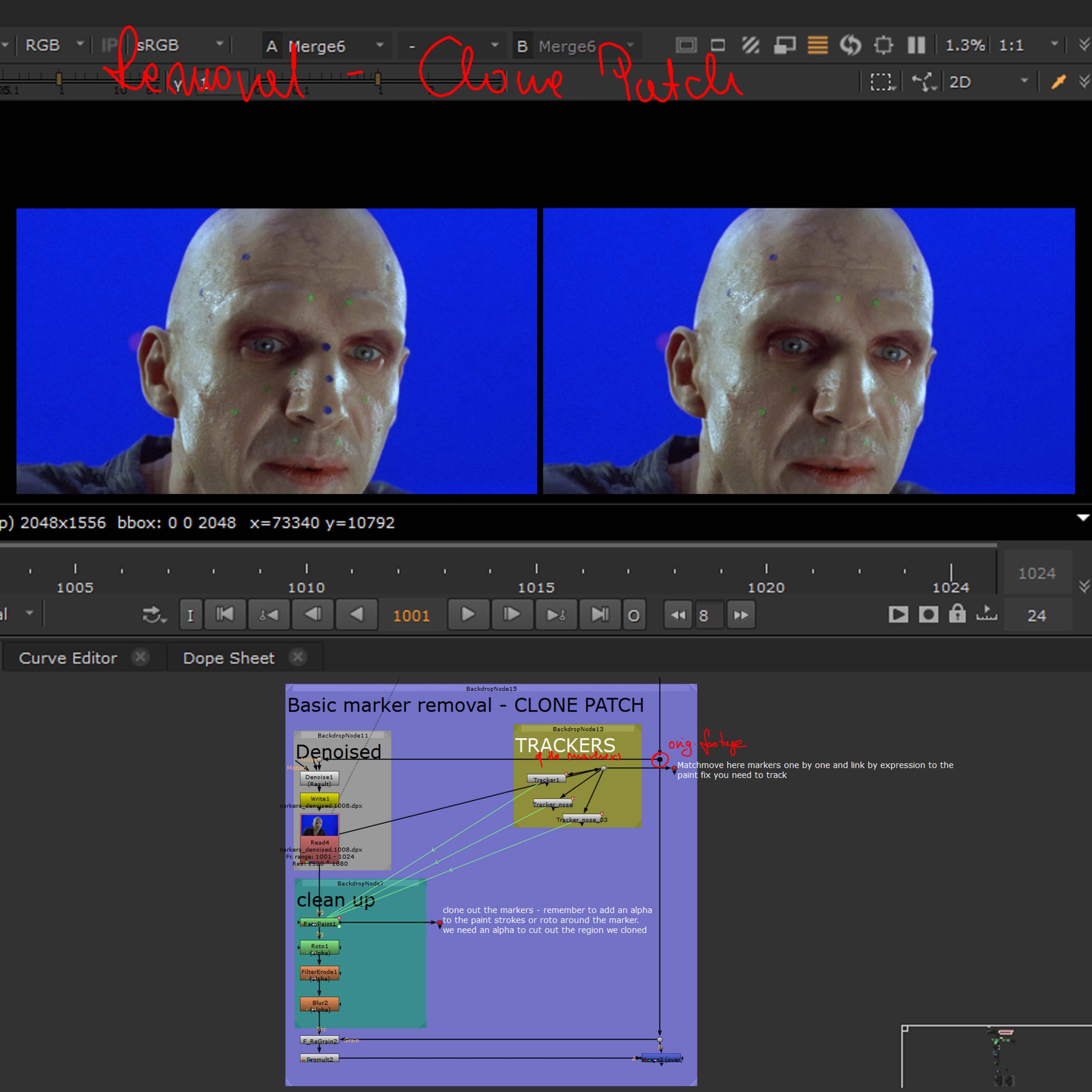
Marker Removal II

The first picture shows one of the more common ways of dealing with tracking marker removal which is based on cutting out a piece of footage (roto), tracking it (assigning to a particular spot) and transforming an instance of the footage to create a patch that shows a neighbouring the marker part of the footage in terms of replacing the marker with that part, which is then merged (over) with the original footage to cover the original marker area.
The second one shows the process of a Clone patch which uses RotoPaint Clone option to create a small painting that covers the marker and matches the surrounding area of the subject that is tracked and assigned to a spot of the footage, and again merges over the original to cover the marker.
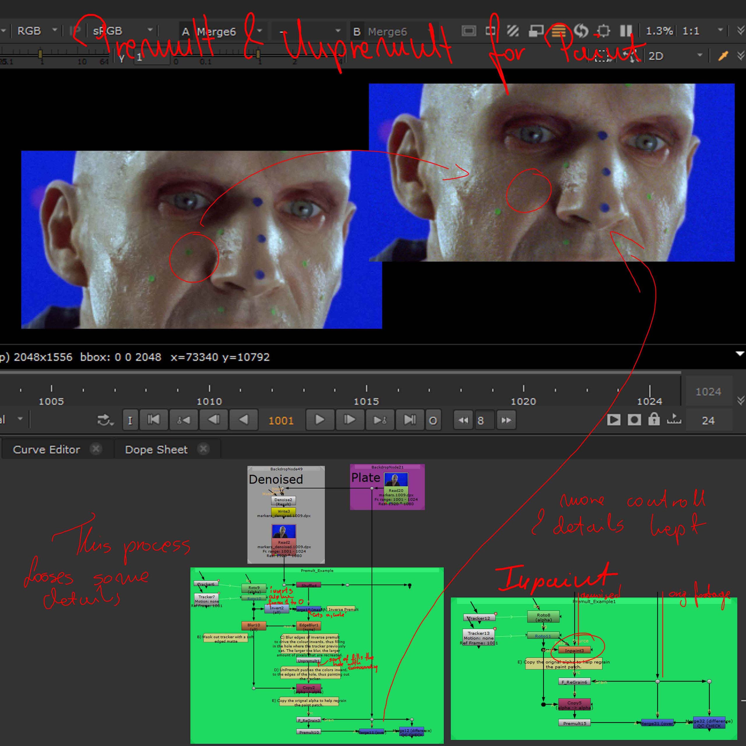
Another way of removing tracking markers is cutting them out and filling the hole through the use of premult and unpremult in the way depicted on the first picture on the left.
The process is controlled by the Blur node and the result changes depending on the amount blurred. Some details will be lost through the use of this method.
Another way of doing this would be through the use of a Inpaint node which works in a similar way but keeps more detail than the previously mentioned technique.
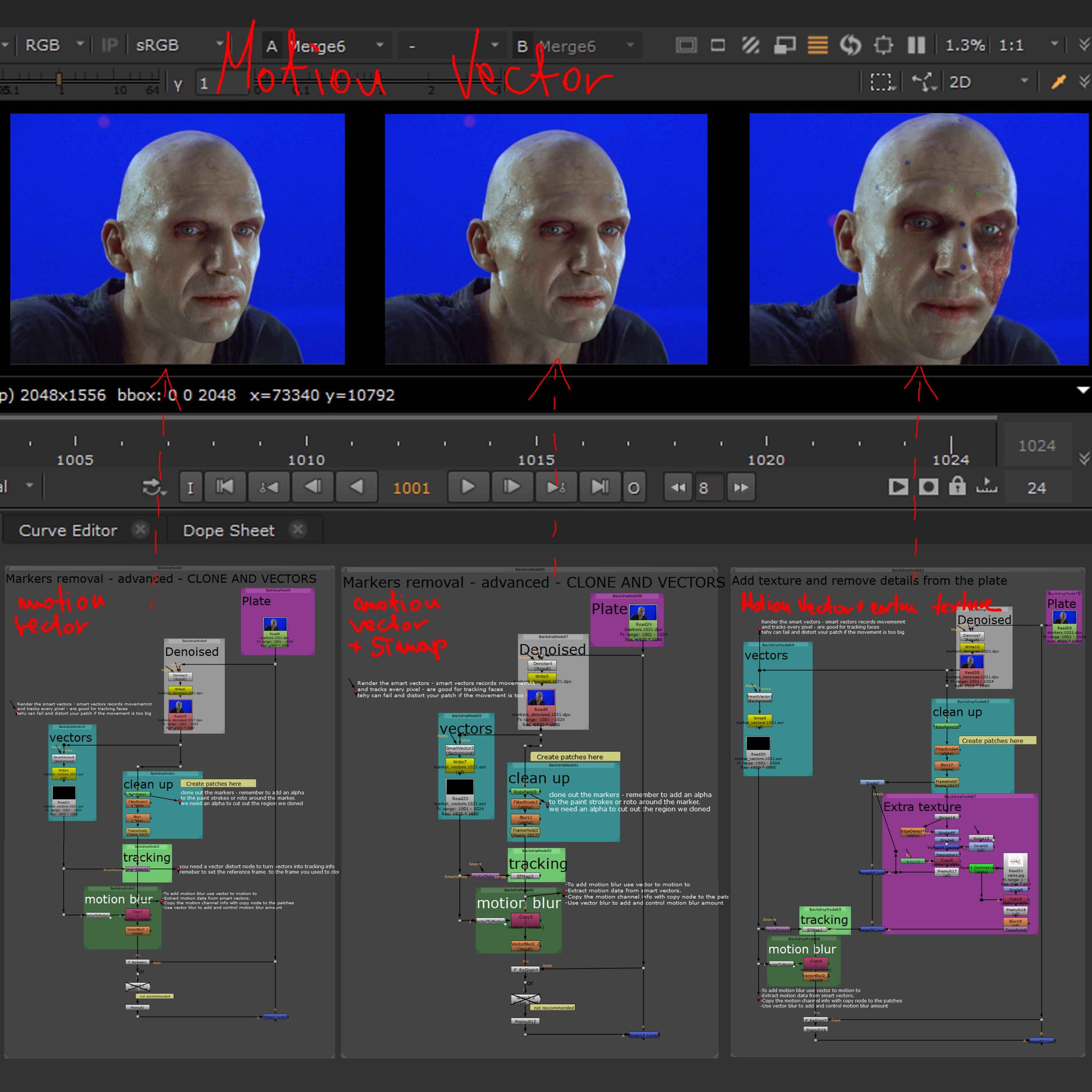
Lastly, Motion Vector node creates a map that tracks the movement information of the footage pixels placing them within groups divided through colour information, which then allows for easy application of RotoPaint patches to the right area of the footage. The second version on the second picture uses STMap to decrease the heaviness of the node and optimise the script. The last part of the script from that picture depicts the workflow of using the MotionVector track information to add extra texture to the footage after the clean up part as well as adding motion blur and re applying grain.
UV Map introduction
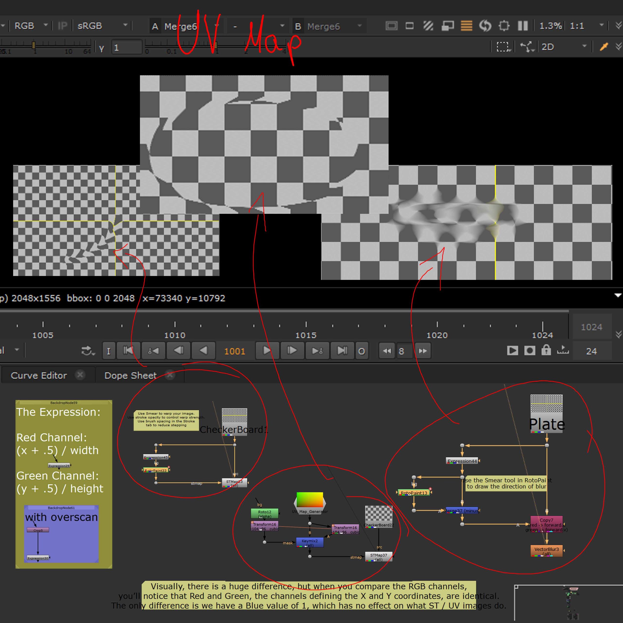
The picture on the left shows a quick recap on UVs in general and introduction to UVs and STMaps in Nuke. The CheckerBoard and simple roto were used to illustrate the way those elements work in practice and to show their influence on a image (as shown on the top part of the picture).
Beauty Work
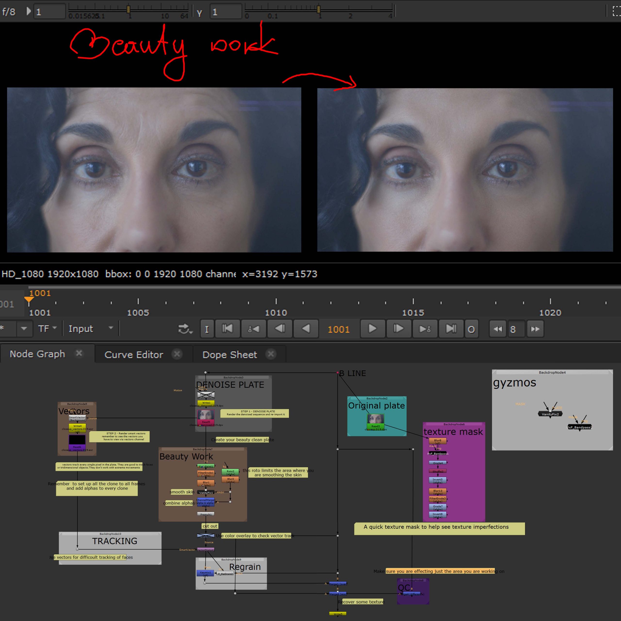
Beauty Work is one of the more common tasks in Post Production, it ensures the footage is presentable and that the subjects simply look good. This type of comp is very subtle in terms of keeping the footage authentic and not artificial and uncannily perfect.
Like most, it starts with denoising and tracking (MotinVector) the plate, to which we later add RotoPaint and Roto to remove whatever needs to be removed. There is a few gizmos which can help with the general beauty workflow in terms of fixing small skin imperfections etc.
In case of requirement extra texture can also be added at this stage of the work and then the finished footage is regrained (keymix to work with alpha only and not add extra grain to the rest of the plate) double checked and merged with the original.
Excercise
Week 3
Matchmove
Matchmove centres on preparing the script for CG and further work, for which the clean up needs to be finished and basic geometry (cards) as well as tracking should be provided.
Matchmove is also responsible for setting up the project in terms of applying the supplied information about the footage in the project settings to make sure the whole will work together and match the way it is supposed to do.
Lens Distortion
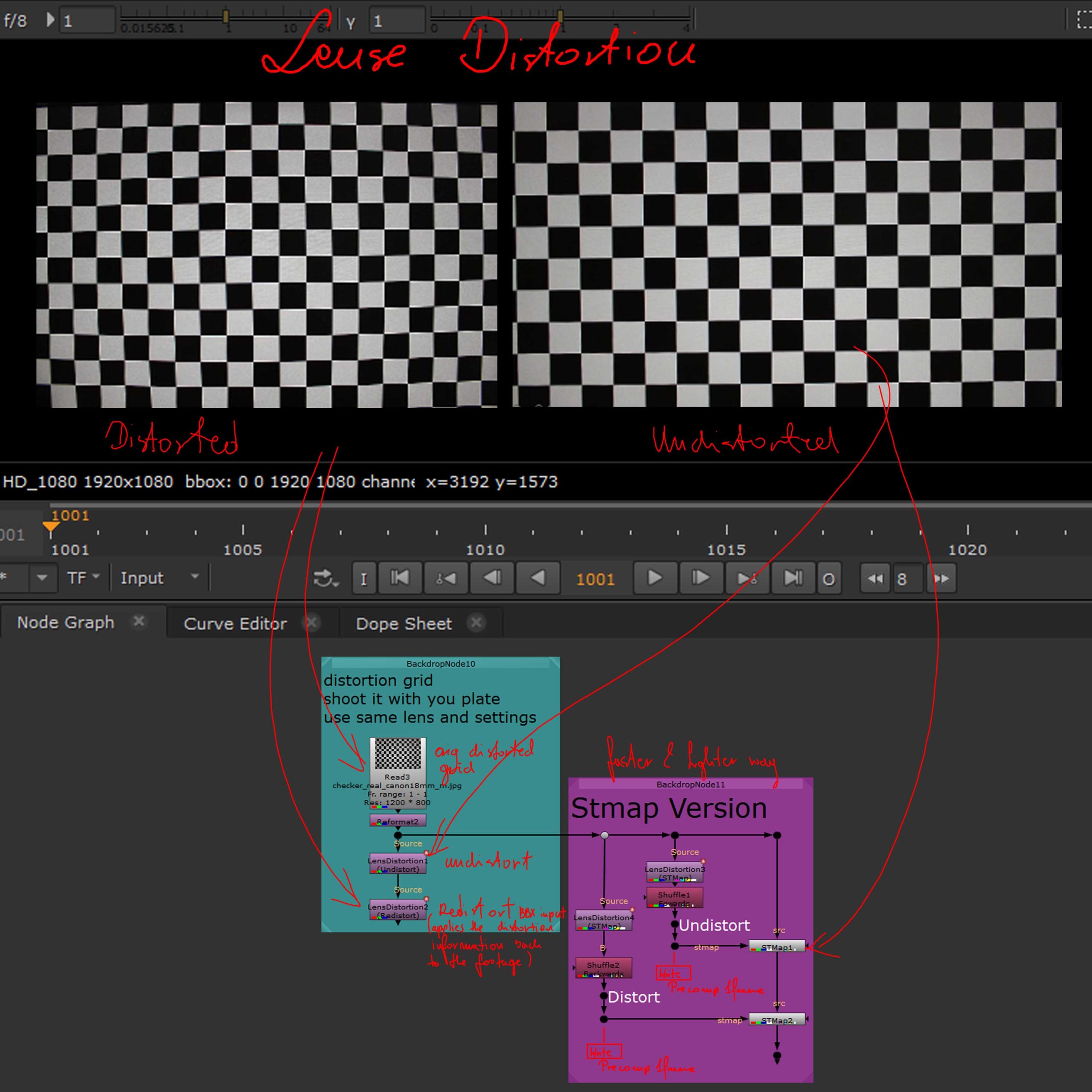
Lens distortion is a optical deviation from linear projection, meaning, the subject, which in reality has straight lines, will loose them to a slightly curved ones, due to the curvature of the lens (and its general parameters) through which it was captured.
In VFX work it is important to apply any CG to an undistorted version of the footage, to which the distortion is later re applied when the work is finished, ensuring a good match between the CG and footage.
3D in Nuke Intro
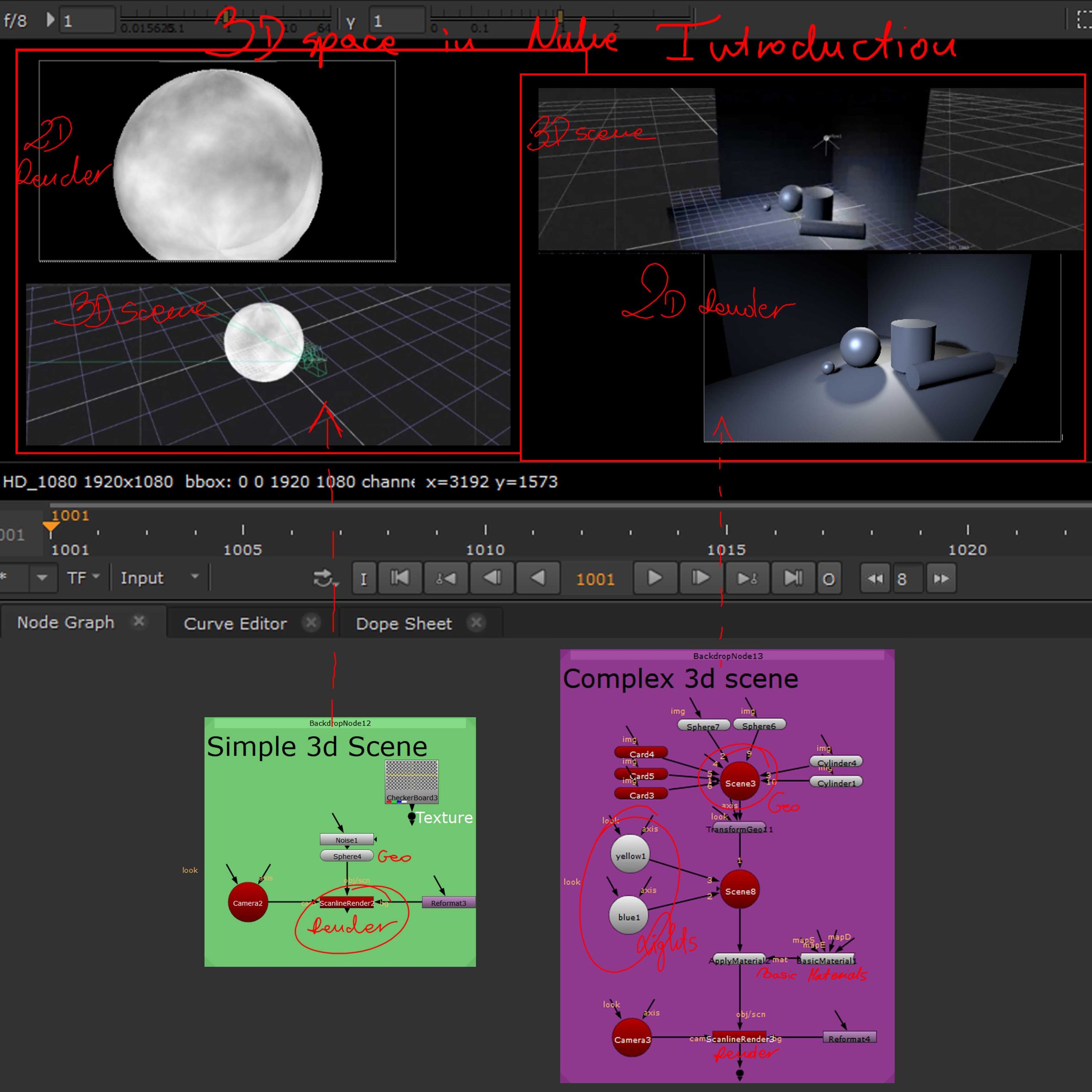
This screenshot introduces a couple simple 3d scenes containing basic geo, lights, materials, cameras and scanline render which is a node that translates 3D to 2D.
Matchmove
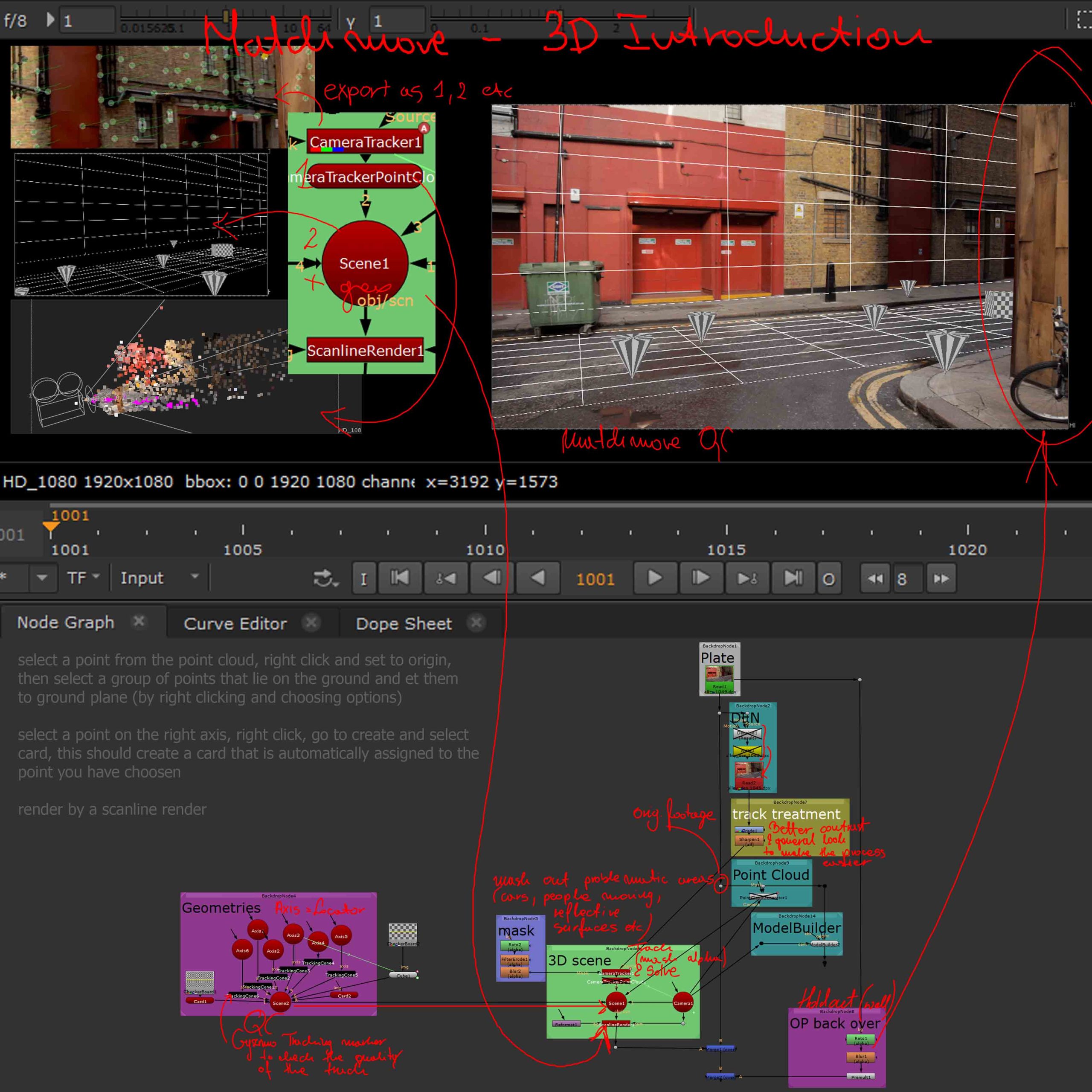
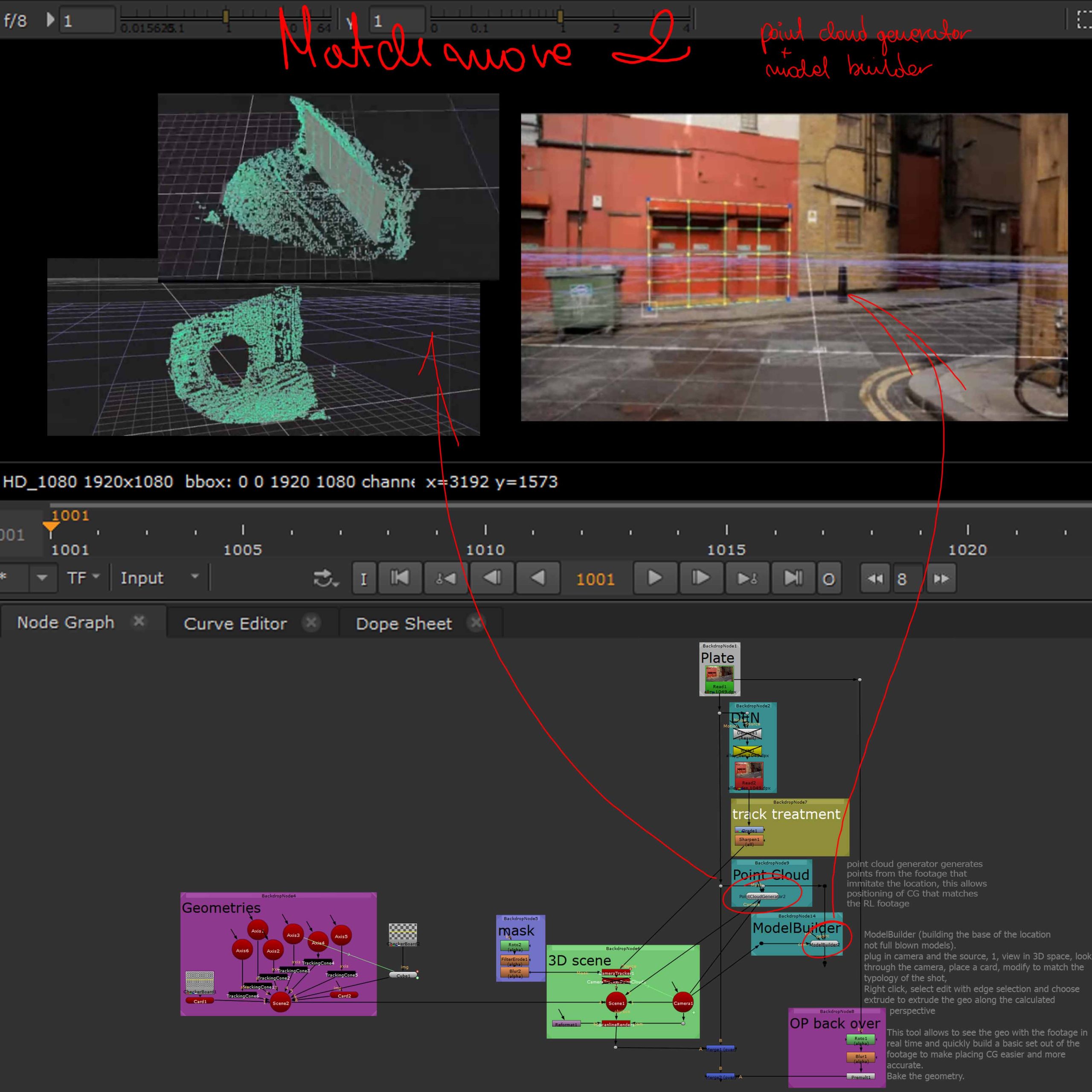
The first image introduces basic ideas and tools for matchmove as well as puts those into practice by working with footage and describing a whole matchmove workflow as visible in the bottom part (script).
The second one highlights the way Point cloud works and how helpful it is in terms of rebuilding the footage structure in CG, as well as it introduces the ModelBuilder node, which allows to create simple geometry while viewing the footage.
The idea of matchmove is to supply a base for the CG addition into the shot and to be able to match the elements seamlessly it is important to be able to pinpoint where exactly the subjects of the footage would lie in the relation to the CG so we are able to place the CG in the right spot. This is achieved through many tools but mainly started with a track and point cloud creation which places points of the footage within a 3D splace which allows for the placement of cards and other simple geometry as place holders for wall, floors etc, giving a solid reference base for the CG.
This is also a base for replacing elements of the footage, for example adding texture to a wall would be started by placing cards in the right 3D spot corresponding with the wall indicated by the point cloud.
Excercise
This weeks exercise will be placed at the bottom of this terms blog page as it is a part of the bigger project in works.
Can be found in the ‘Work for the Machine’ section of this page.
Week 4
Projections
Projections are the easiest way to replace parts of the footage, they are done by projecting an image (or a desired frame of the footage) on a 3D element (mainly a card) with the use of a projection camera.
Projections
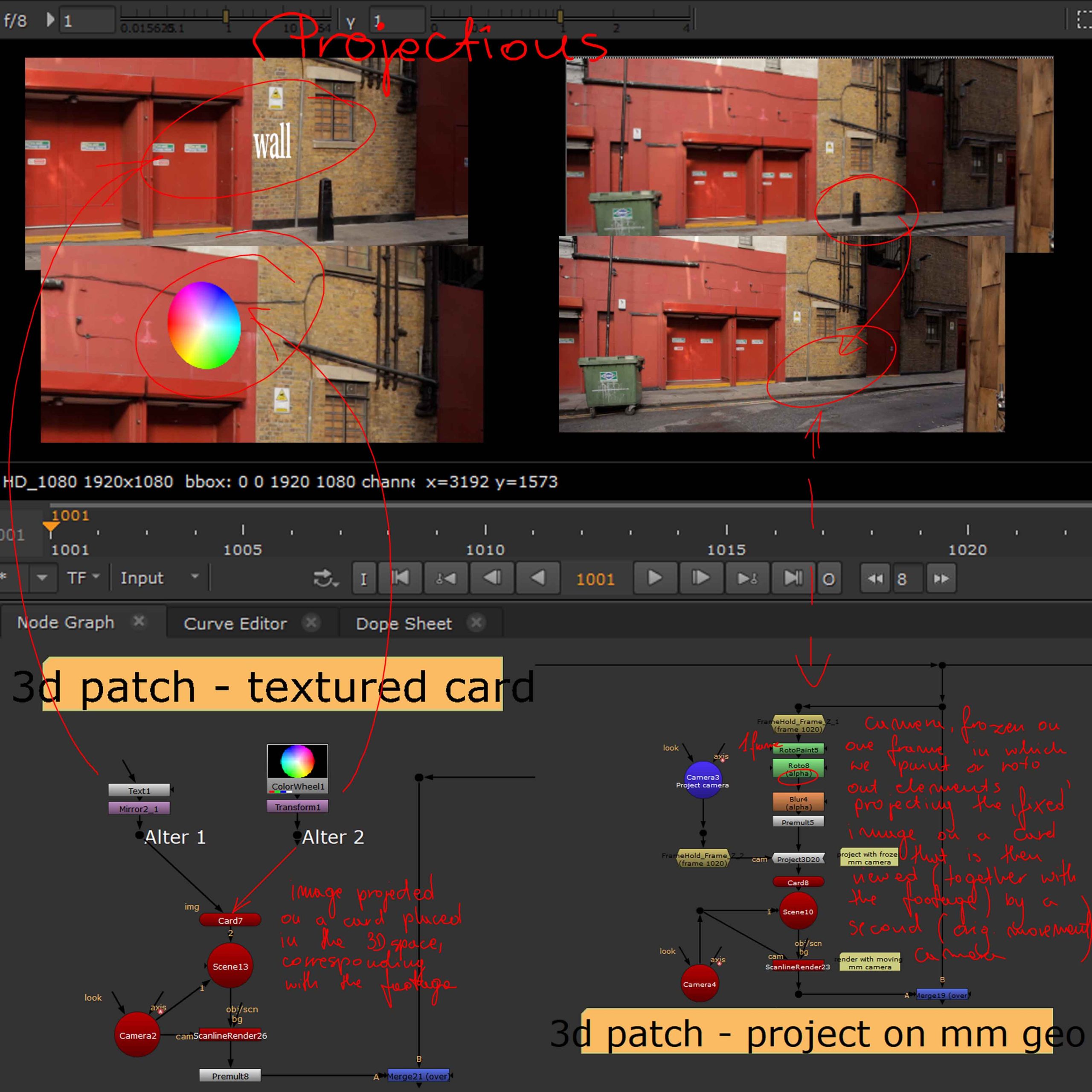
The first picture (left) shows first two methods of using projections in compositing work, one of them simply places an image on a 3D element (card) corresponding with the footage whereas the second one uses a projection camera frozen on a single frame to project desired image (RotoPaint Clone painting covering the pole) on a card corresponding with the wall from the footage.
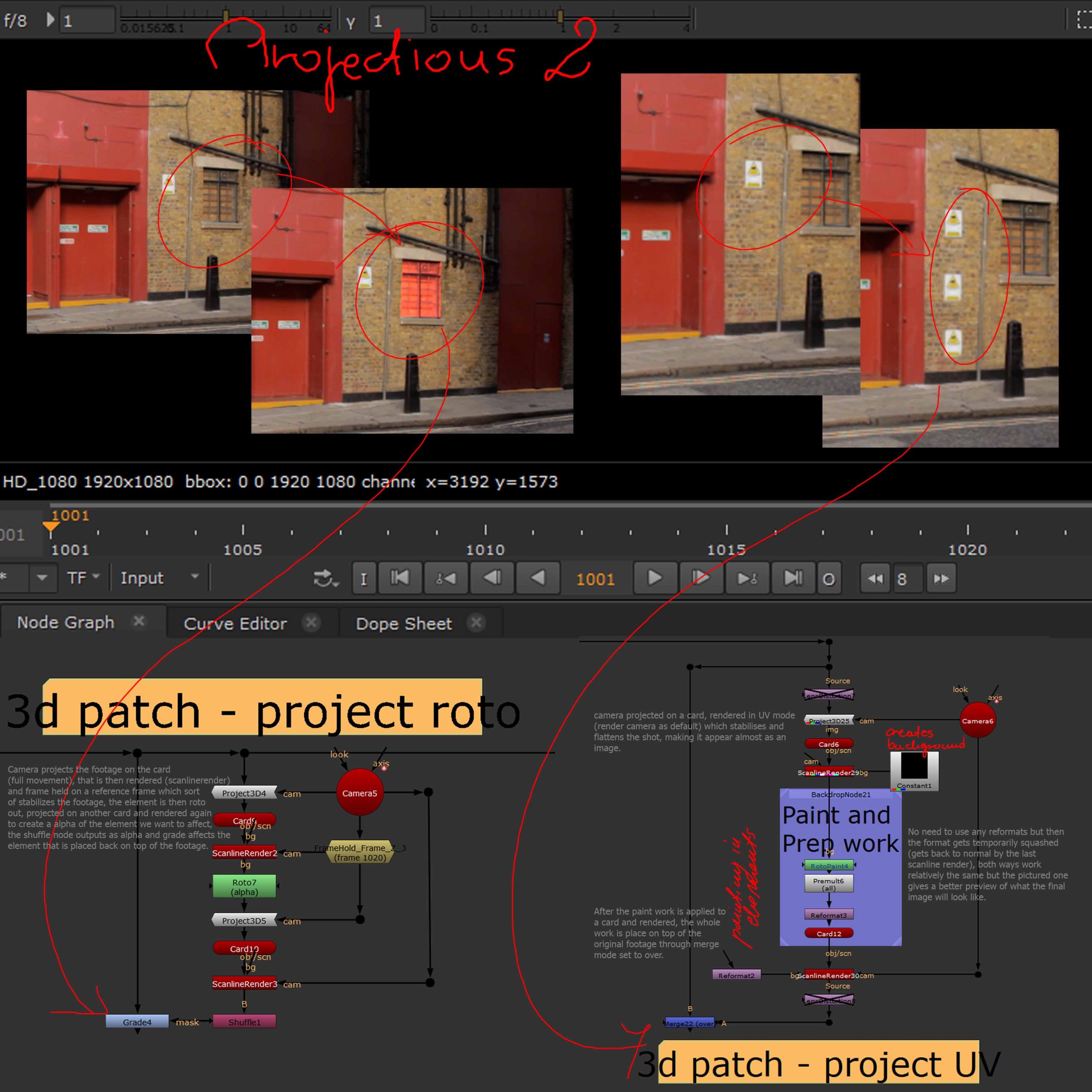
The second screenshot demonstrates the workflow of further two techniques, one, FrameHolding a ScanlineRender in terms of stabilising the footage (and further working with that – in this case roto and a grade colour change) and second one, similarly stabilising the shot (in another way) to later clone and paint in additional elements.
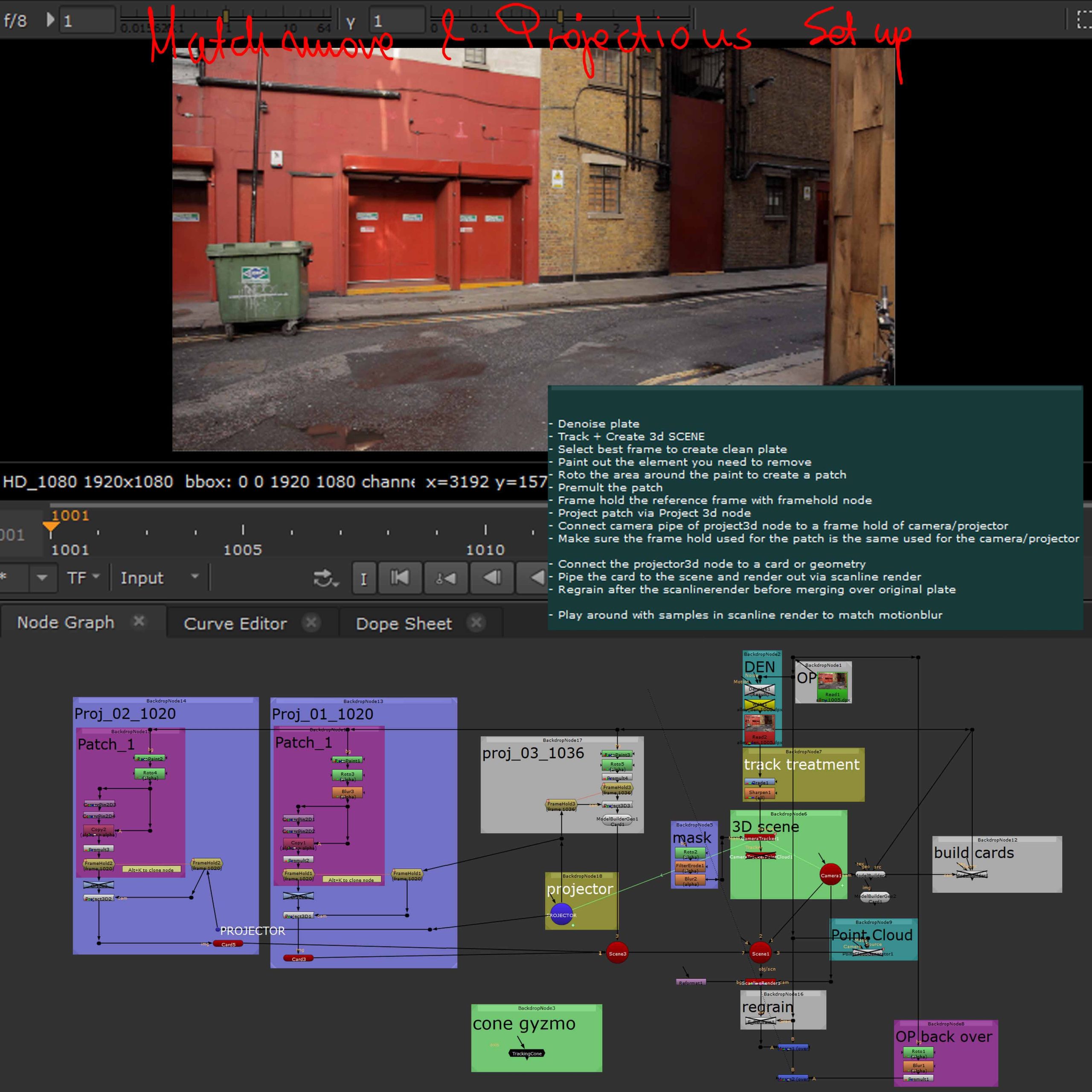
The last picture (right) shows the general set up and workflow for matchmove with 3 projections (employing the previously discussed techniques).
Week 5
Projections II & Day to Night
Types of Projections
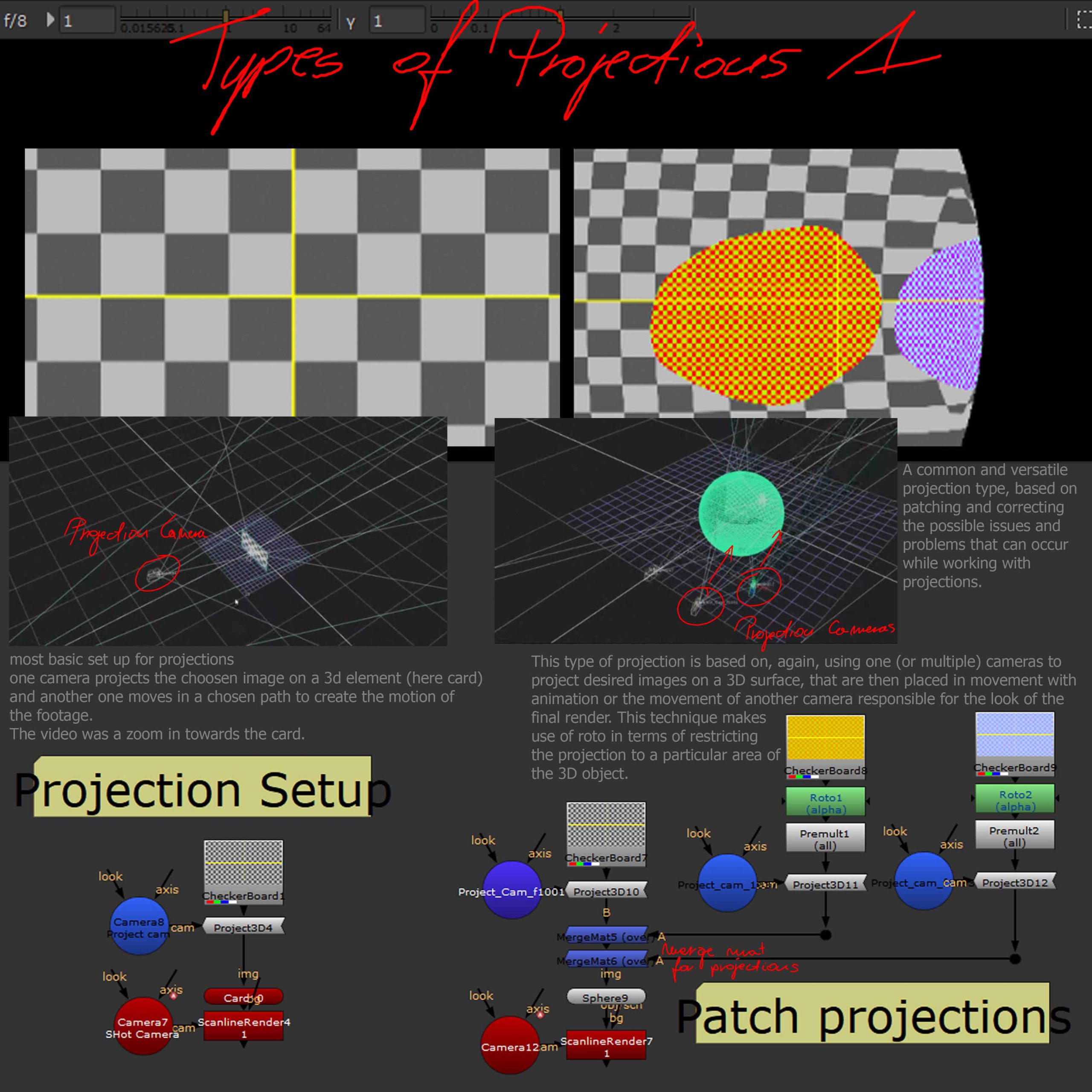
There is three main types of projections each meant for a different outcome and use.
The left part of the first picture shows the main basic set up for projection workflow that is a base for all the main types.
The first type, patch projection is the most common and is based on using a camera for projecting the desired image on a chosen 3D surface.
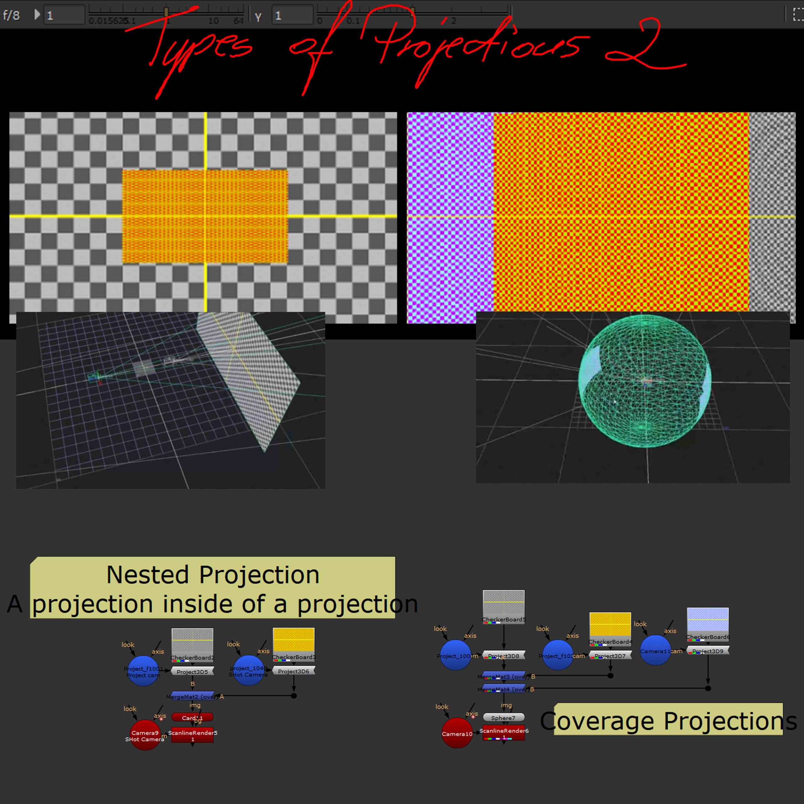
The second picture shows remaining two types, which are nested and coverage projections which, both mostly make use of multiple projections that are then merged and projected on a 3D surface and rendered out. They have different uses, the firs one, nested projection is mainly used for zoom in shots whereas the second one, coverage projection is used for panning shots.
Projections issues
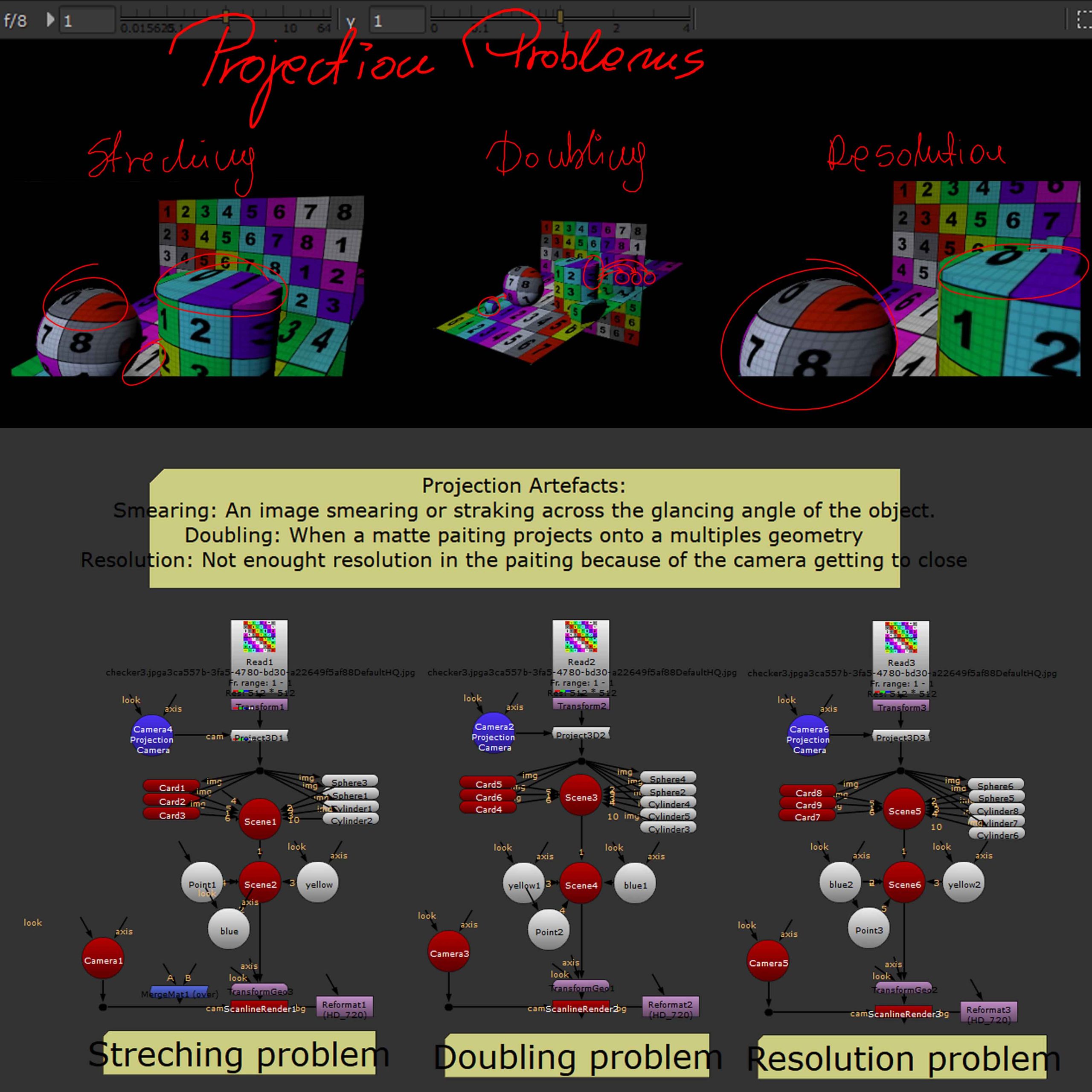
Based on the placement of the projecting camera as well as the choice of a wrong reference frame, sometimes, we can end up with an array of different issues that stop the outcome from feeling realistic and sometimes simply loosing resolution.
Most common issues are; 1, stretching, where parts of the image stretch unnaturally on parts of the geometry, 2, doubling, where the image is projected multiple times over geometry, copying the picture and reapplying it to the further parts of the setup and 3, resolution, where we simply loose resolution in one part of the setup dues to the distance of that element in relation to the projecting camera.
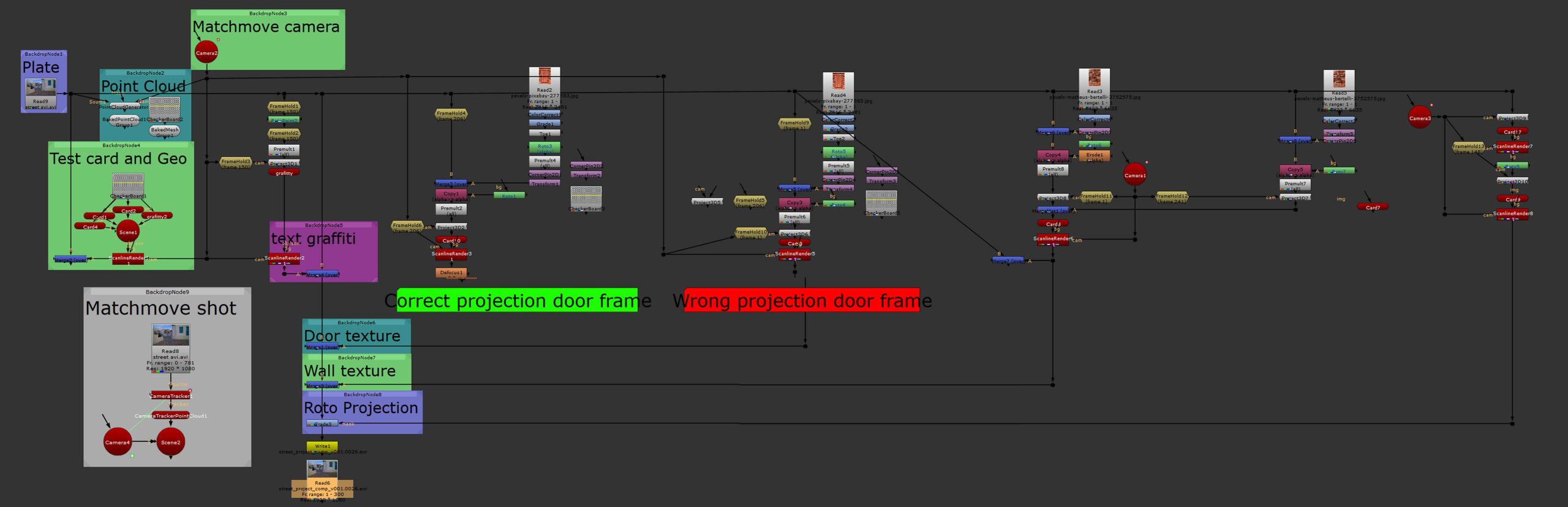
Projections in practice
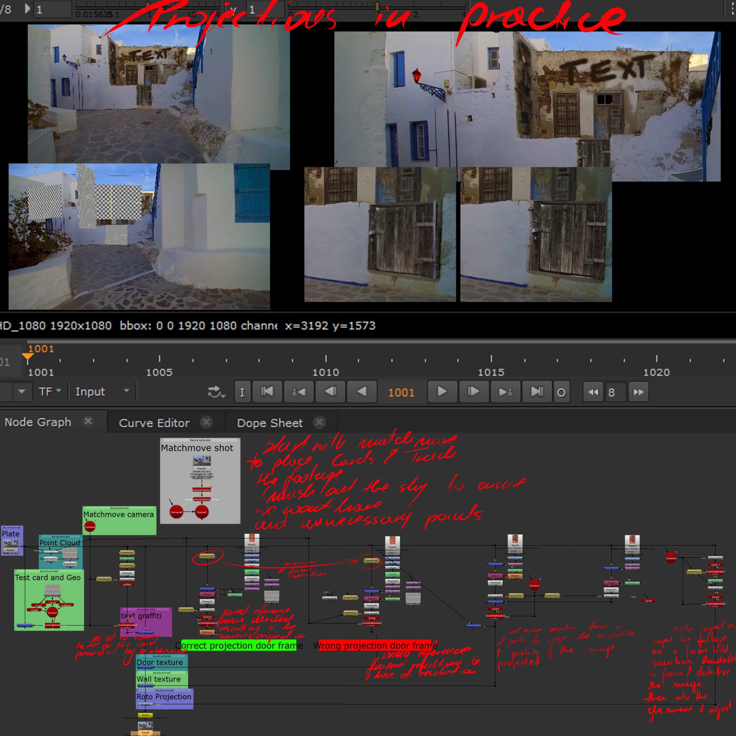
In practice projections come after matchmove and are placed on cards prepared in matchmove.
The screenshot on the left shows the process (with the script in detail below) containing the right and wrong way of projecting highlighted.
The first part shows the placement of a simple text or graffiti on a wall of a building done by frame holding and projecting on a 3d card, which is later rendered and merged with the original footage. The next part discusses the importance of choosing the right reference frame in terms of avoiding some of the problems discussed previously (is project form afar the projected image will loose detail). Which is followed by the last section in which roto projection is demonstrated, where the image is first stabilized in terms of easier roto that is later graded to achieve a change of colour of an element of the footage (discussed in more details in the ‘projections’ section of week 4).
Original footage
Compositing outcome
Discussed in the section above elements in a video to present the final practical outcome of the process.
On a side note the stability of the projections and 3D elements (cards) depends on the quality of the matchmove.
Day to Night
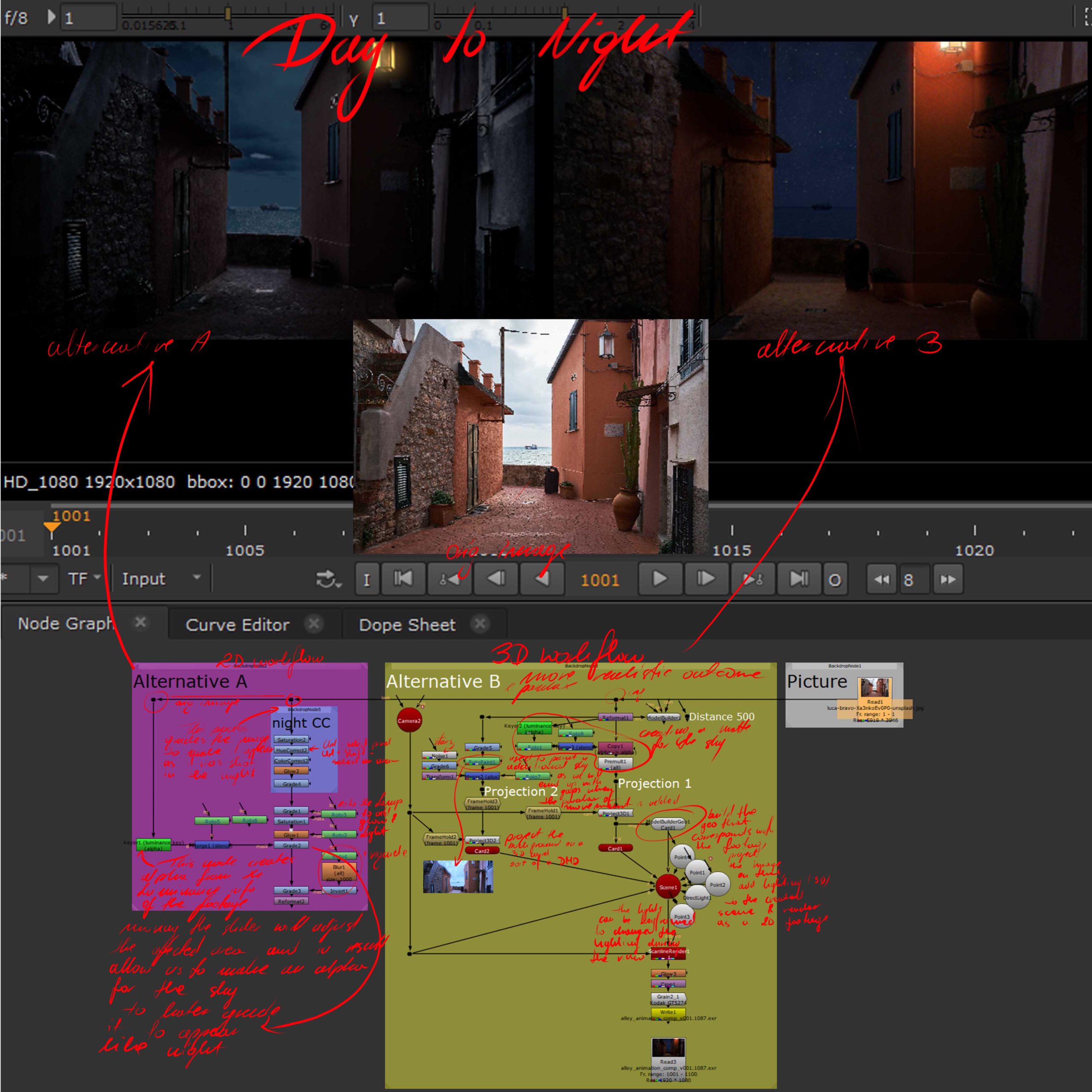
This screenshot depicts two ways of changing the lighting of a footage, one (left) in 2D (suitable in some cases but can give slightly flat and artificial results) and the other one (right) done in 3D (in general better but also heavier results).
Both of them are based on grading and using mattes to separate elements in terms of further grading them to achieve more convincing results. The first one uses a keyer (luminance key) and roto to separate the sky, in terms of further darkening that area without going to dark with the foreground, and the other one goes a step further and through using the keyer, roto, modelbuilder and projections it recreates elements of the footage in 3D which then can be relit with the use of 3D lights, resulting in a much more realistic behaviour of the environment.
There is also simple movement added to the image in terms of making it into a footage, the first method simply scales the scene up, but the second one adds subtle camera movement (into the built scene) which allows some parallax adding depth to the movement and image.
Week 6
Render Passes
AOV’s and the possibility of separate grading
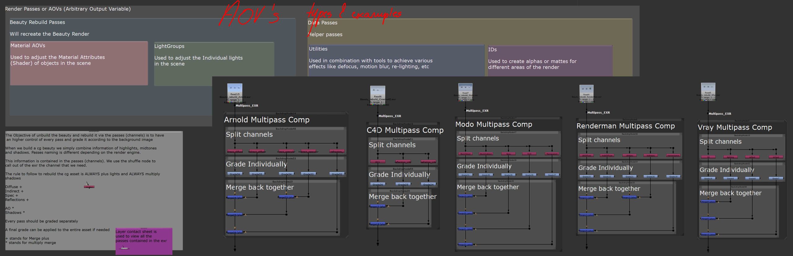
Introduction to AOV’s and the separate treatment of different elements of one render. This screenshot explains the groups of AOV’s as well as introduces different possible passes we can employ in our workflows as well as the idea of separate treatment of elements.
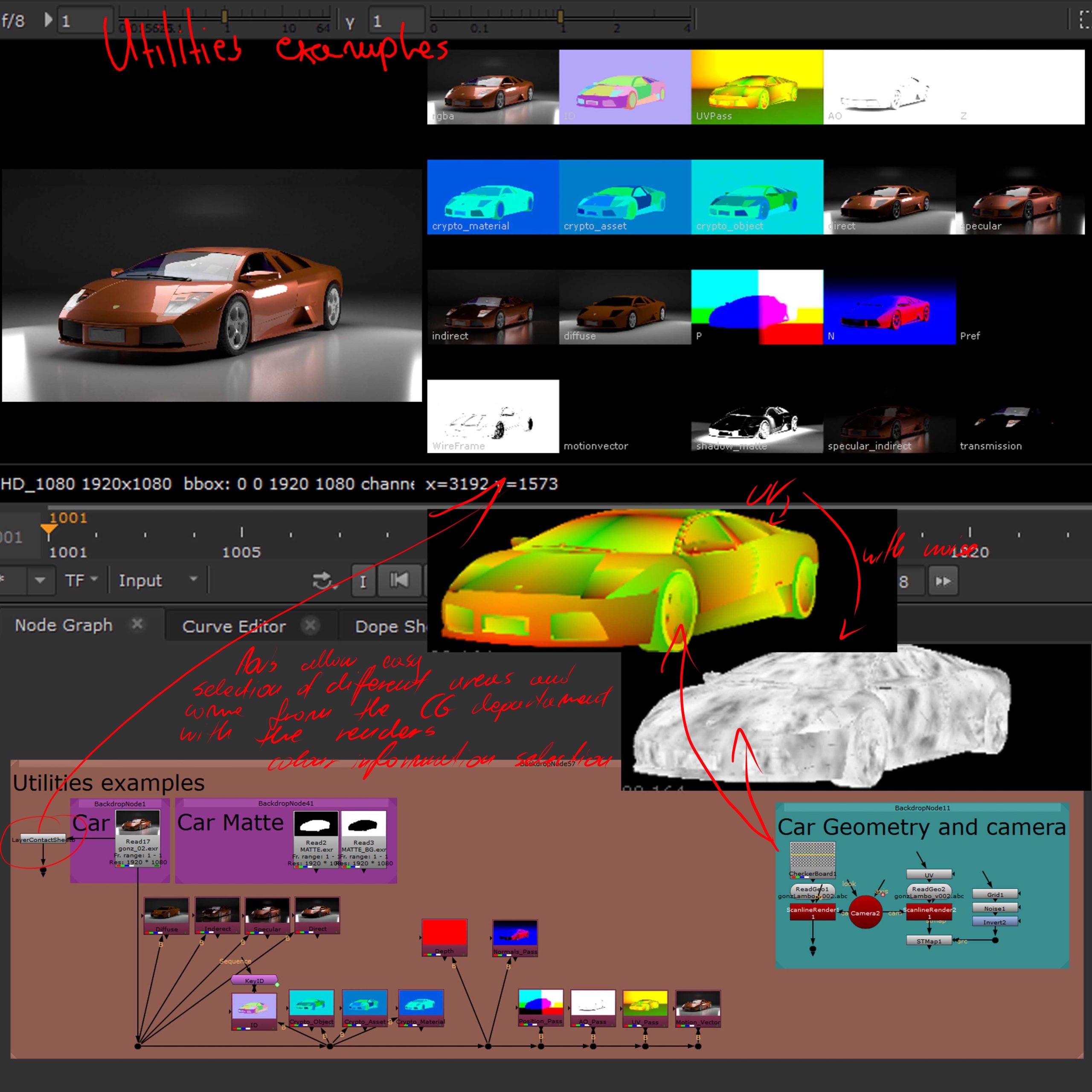

This part of the lesson introduced the LayerContactSheet node which allows the viewing of all available within a render passes alongside their names. This also briefly explained the process of working with different AOV’s and the way they can be used as well as their general purpose. Here we also discussed the practical uses of UVs within Nuke.
Putting theory into practice, this screenshot shows basic workflow based on separate treatment of different elements within the render. The left side focuses on the colour correction of specular channel only and the right one on the diffuse, in terms of explaining and introducing the power of such work and treatment.
Finally, a practical example of the discussed workflow, taking two separate images (one of which is a CG render) and through colour correction and grading adjusting them to make them appear like they are a part of one world, like they were meant to be together or like they were just photographed together.
Relighting
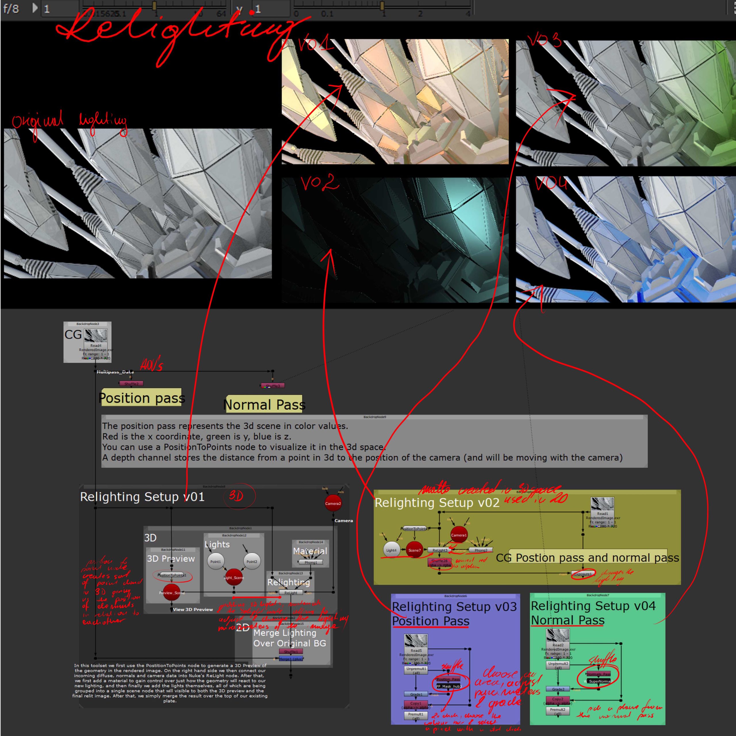
Discussing different ways of relighting a scene using different processes and tools.
V01 uses a 3D set up and conversion of the image into a point cloud (position to point node) which is then relit adjusted in 3D through adding lights and materials to then, through Relight and later merge nodes be merged together into one newly lit image.
V02 creates a matte in 3D space similarly to v01 with the difference that that 3D matte is then used and treated in 2D (shuffle alpha and exposure).
V03 is based on the use of a position pass with a gizmo that allows the selection and adjustement of particular areas that match (and neighbour) the position selected from the map.
V04 similarly to v03 uses normal map and a gizmo, again selecting and treating the selected and adjacent areas.
Week 7
CG integration
Set up – on the example of the CG machine project
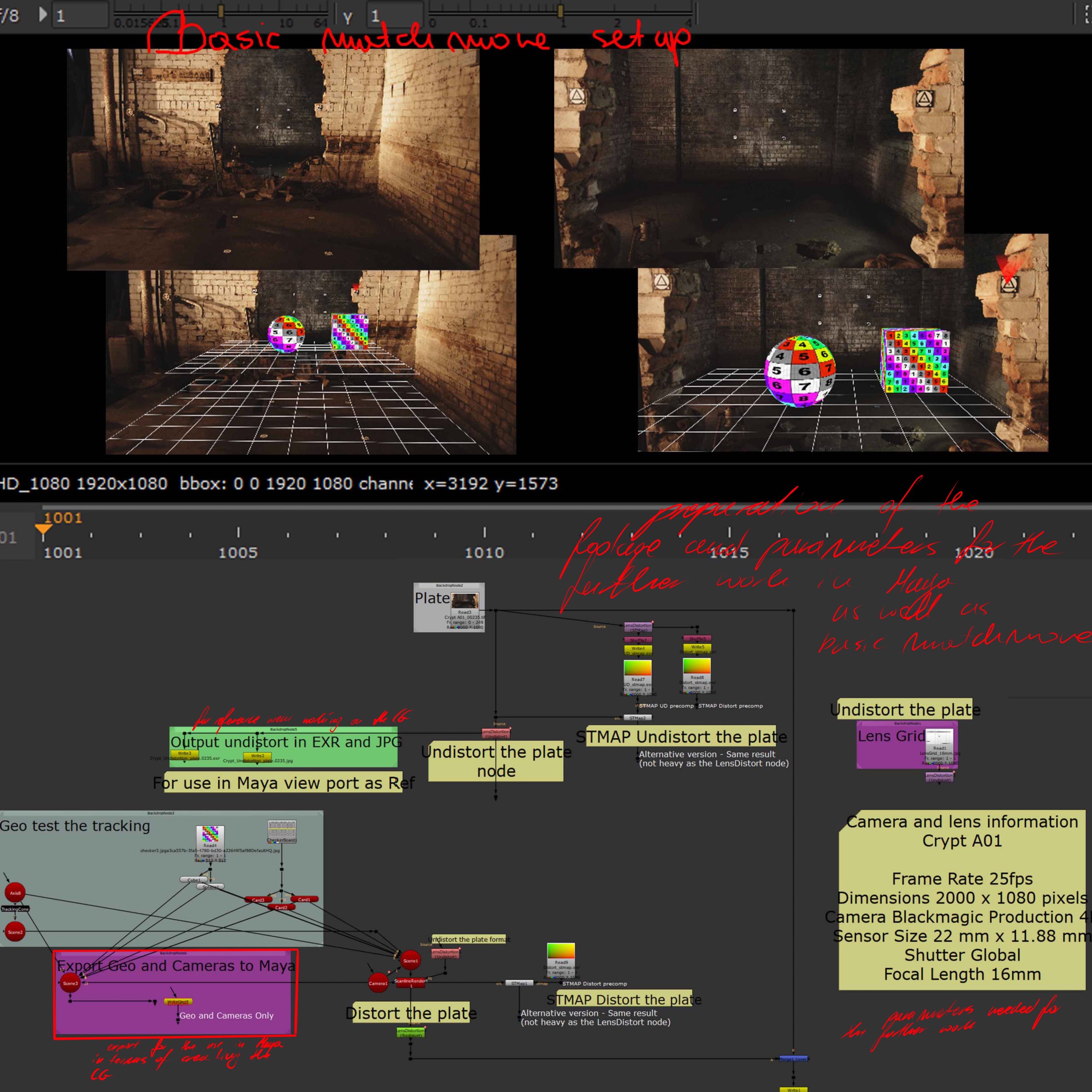
Basic matchmove and preparation for Maya workflow as well as the information for the project setup (right of the first picture) all previously discussed in more details in the matchmove sections of this page.
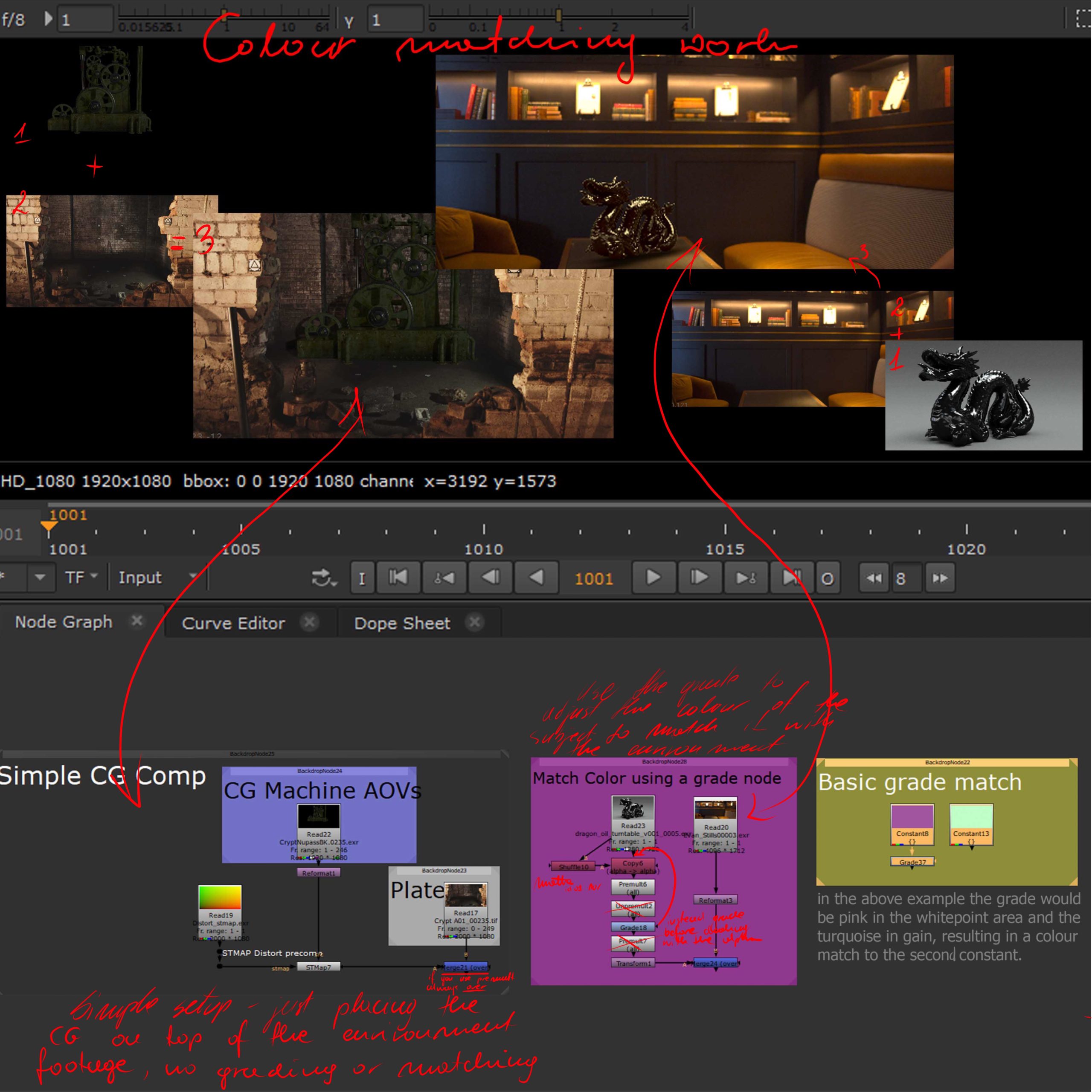
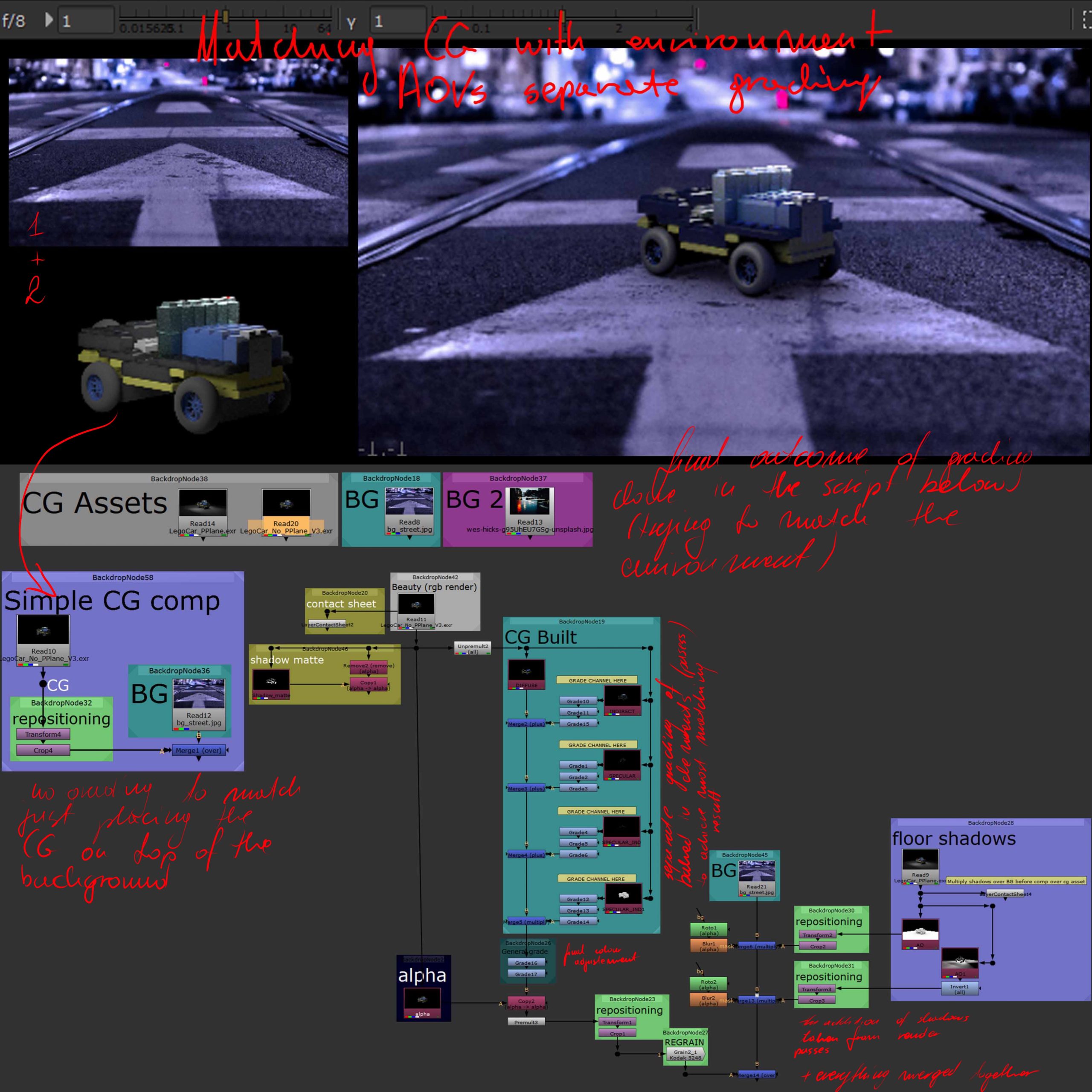
Colour matching in CG integration
The left side of this screenshot shows the most basic CG integration process with no grade or colour correction to match the two together.
The right side on the other hand focuses on the possible ways of matching the two elements together through transformation and colour correction of the elements in question.
It shows the way of using different render passes in practical setting and the way they can be graded to optimise the workflow and come up with successful results.
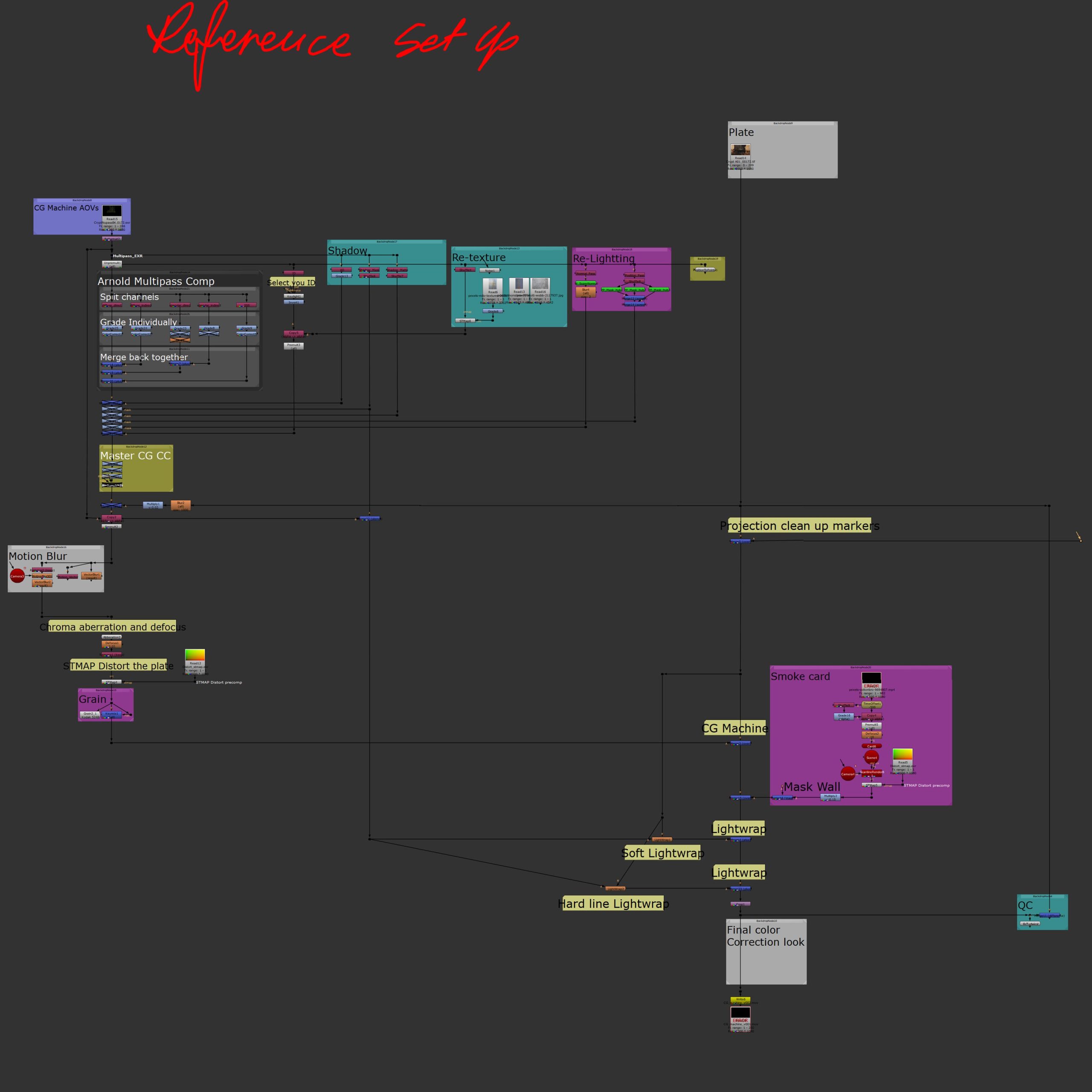
The general main reference set up of the process, shows the order of actions as well as introduces some of previously discussed techniques in a practical use (relighting, retexture and shadow work), applying them into an actual project with a purpose of matching the CG with the footage. It also introduces new concepts that allow a better match with the environment (chroma aberration and lightwrap).
The script discussed and displayed in more detail below.
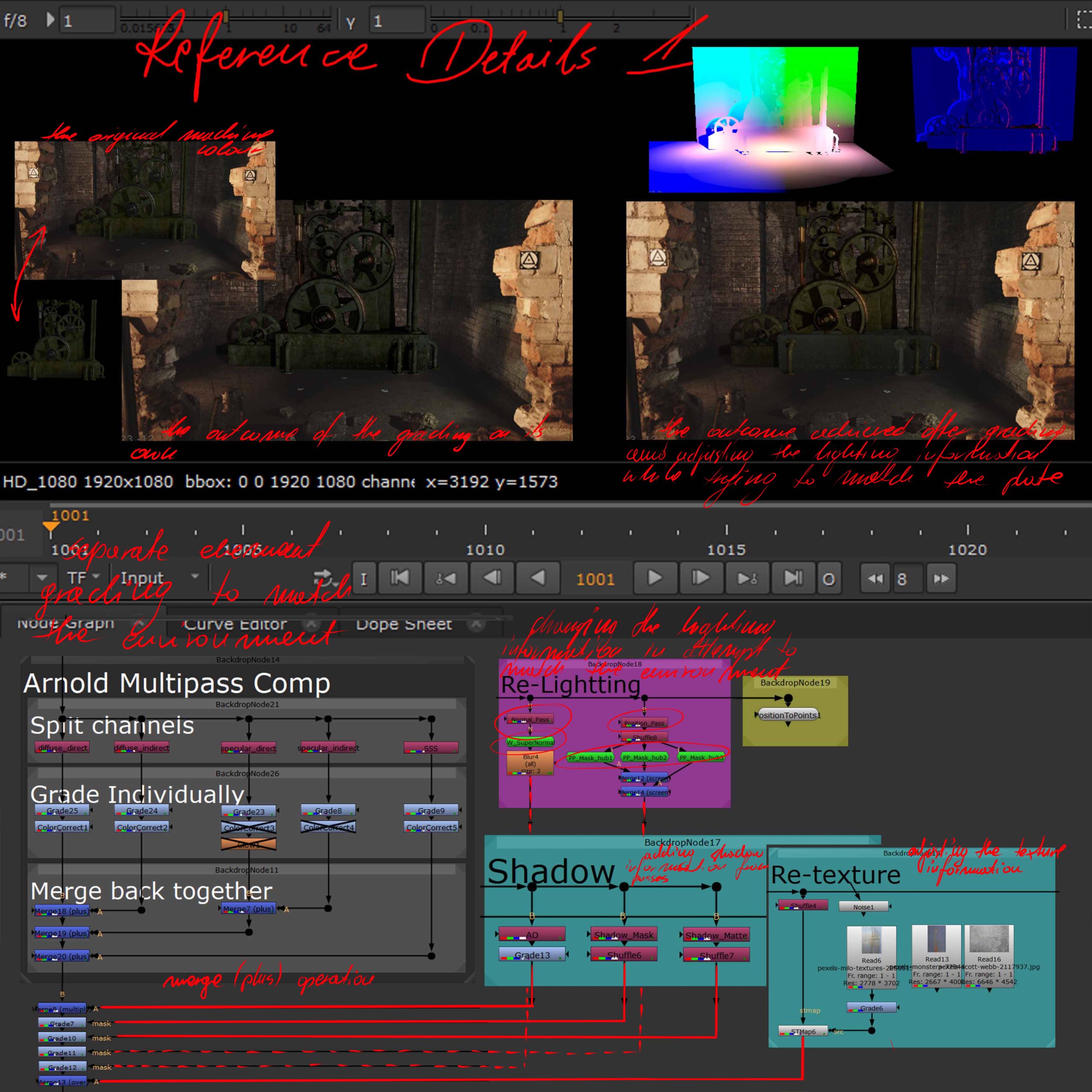
The first stage of the script focusses on the colour correction first showing (from left) the original elements without any colour correction work, followed by graded and corrected version and later by relighting outcome.
Starting with grading passes individually according to needs in terms of matching the plate, then relighting, retexturing and work on shadows (all based on grading and adjusting render passes).
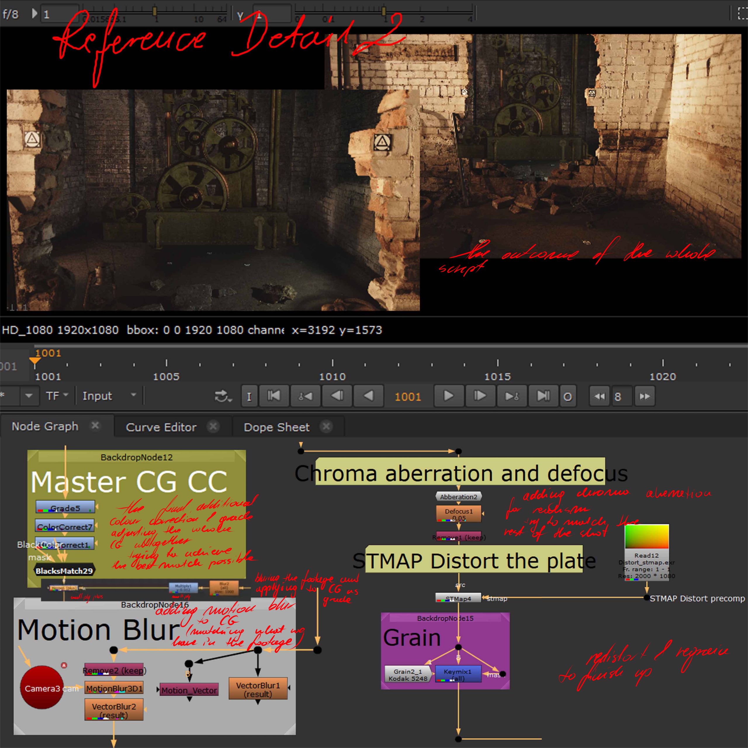
Then followed by master CG colour correction, now treating the whole element of CG and further adjusting the colour, moving on to the addition of motion blur to the CG, chroma aberration (matching the one from the original plate), re distortion of the whole and re graining the image.
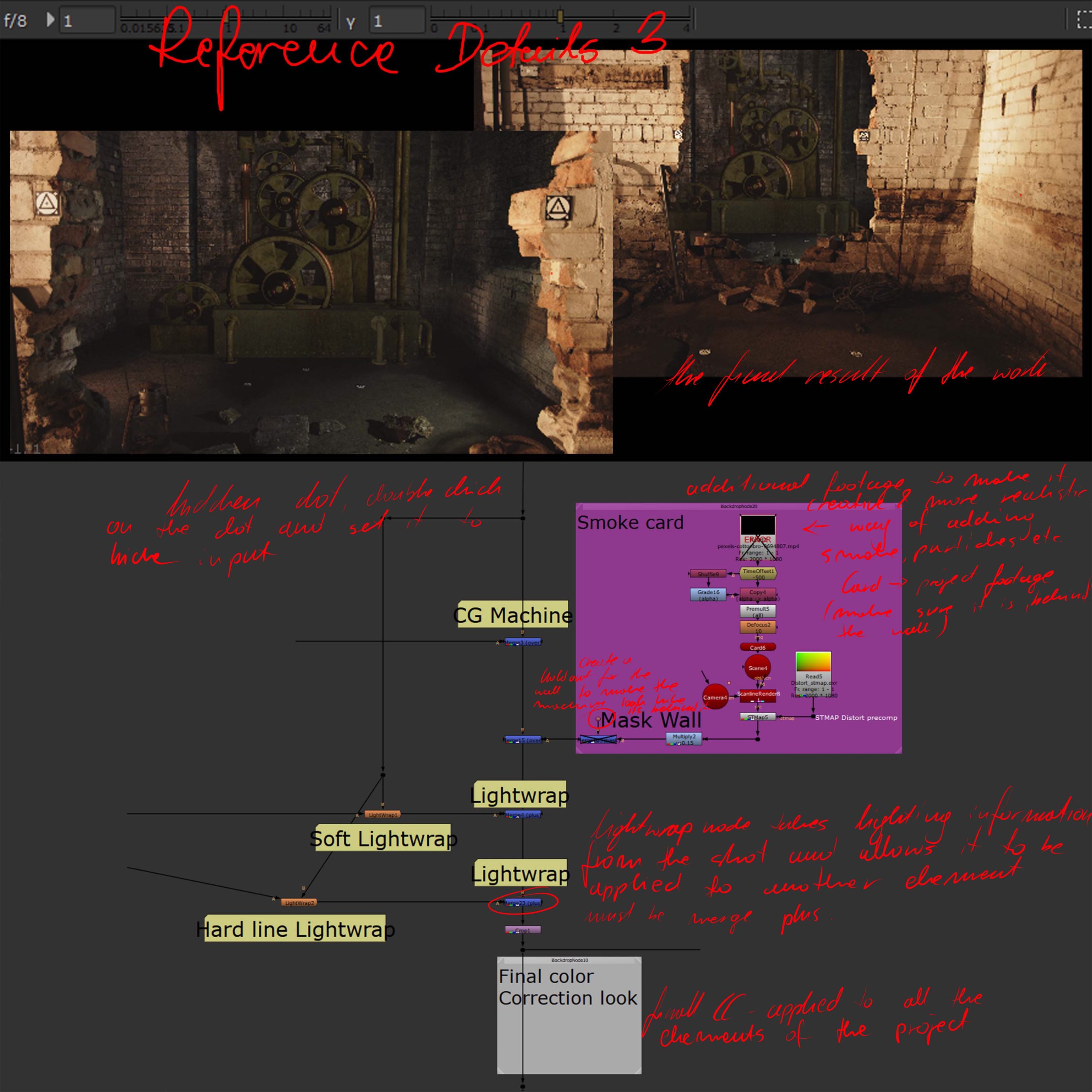
The whole process finished up with the addition of a wall matte holdout (not in this example but needed here to place the machine behind the wall and make sure it is not sticking out from either side), addition of smoke and particles footage on a 3d card placed in the right part of the 3D space of the footage (possible not needed) and lightwrap to further match the lighting of the original shot on the CG element.