
Nuke Fundamentals
First project of the course, concentrating on the basics of the VFX industry, and so, teaching essential skills and techniques within the industry standard software. The unit contains technical workshops for skill development in Maya, Nuke and 3D Equalizer, as well as research tasks concerning the historical and possible future context of VFX, all accompanied by evaluation of own work.
All pictures can be enlarged by clicking on them.
Week 3
Cinematography Intro I
Creating a successful moving image, whether it is CGI or live action based, the filmmaker needs a solid base of understanding the mediums and workflows used within the entire process of creating the film. The basic camera functions connected to the lighting, lens angles and distortion are discussed in detail in a link accessible by the button directly below.
Digital file formats
A file format is a standardized way of encoding the data for a particular purpose. Video is most often stored in a compressed file format, containing both image and audio, to allow the minimal the storage usage. Most common formats in the industry are; MP4 (supported by most, good quality, audio, video, text and stills), MOV (designed for Quick Time Player, stores audio, video effects and text, good quality, large file), AVI (most versatile, good quality, large file size), ProRes (high quality, compressed, widely used as a final format for commercials, HD broadcasting, features, Blue-ray and streaming).
The above formats are not used in nuke or other VFX software, as the industry works with image sequence files instead, this is largely due to the fact that renderers tend to crash and image sequence are more gentle on them than a video file, even compressed one.
Main and most commonly used files are;
EXR – good quality image sequences with high dynamic range and relatively small file size. Created for VFX, it quickly became the industry standard due to which it is supported by many 3D and compositing programs. It supports 32 bits per channel (bpc), it is commonly used at half that, at 16bpc as it speeds up the render time and doesn’t affect the quality visibly. Multiple render passes can be embedded into a single image sequence.
DPX – Digital Picture Exchange, similar to Cineon format, originally used to transfer films into digital versions, without the loss of quality, later enhanced into a flexible format capable of adaptation to industries needs. It is a bitmap, lossless compression file format used for storing image sequences for motion picture and video, commonly used in VFX.
TARGA (TGA) – great quality, widely supported, not HDR file format. 24-bit TGA includes red, green and blue (RGB), and 32-bit TGA file will contain red, green, blue and alpha channels (RGBA).
Tagged Image File Format (TIFF) – in practice it is similar to a mix or EXR and TGA. TIFF’s are widely used HDR formats that support up to 32bpc. They allow a choice between a compression type (not all software allow all types of compression offered, so the decision should be an informed one). Uncompressed TIFF file will take more space than either TGA or EXR.
Additional formats
.bmp – Windows BitMaP
.dpx – DPX
.iff – Maya iff
.pcd – Photo CD Proprietary Kodak format
.psp – Paint Shop Pro
.sgi, .rgb, .rgba – Slilicon graphics
.tga – Truevision TGA
.cdr – Coreldraw
.exr – Open ER
.jpg – jpeg
.pcx – Zsoft corporation
.pict, .pct, .pic – Picture Default for Macintosh operating systems before version OS X
.psd – Photoshop
.tiff, .tif – Tagged Image File Format
.cin – Cineon
.gif – Graphics interchange Format
.pbm – Portable Bitmap format
.png – Portable Network Graphics
.xpm – X-pixmap (used on UNIX platforms with the X Windows system, ICONS in maya)
Week 4
Cinematography Intro II
Mise-en-scene is essentially the design of each separate shot, and ultimately – the film. It is used to convey messages and subtle pointers towards the general mood, atmosphere and the meaning of the scene. Every element within the shot has to progress the narrative and aid the general aim of the work. Each member of the team should have a clear understanding of what they are trying to convey, in terms of making sure nothing is unnecessary and distracts the audience from that main purpose.
Week 5
History of Compositing
Industry hierarchy
Week 6
Rotoscoping and Tracking introduction
Rotoscoping is a process based on manually separating particular subjects or elements of a scene in terms of being able to place additional elements in between them and their background.
Setups and check graphs
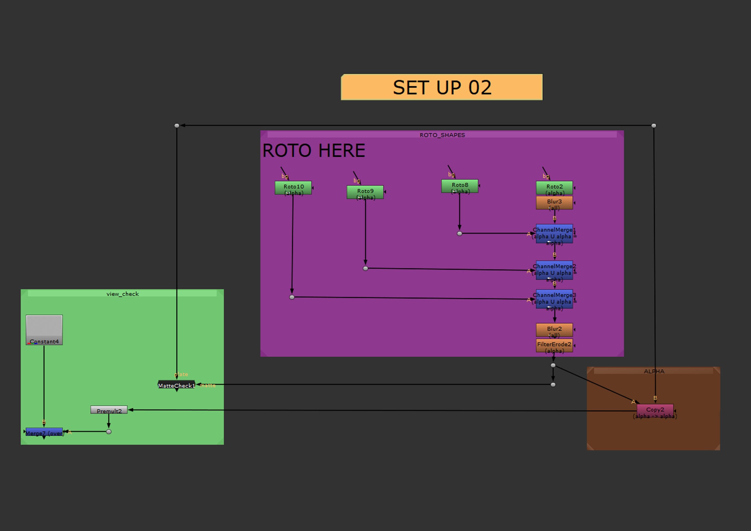
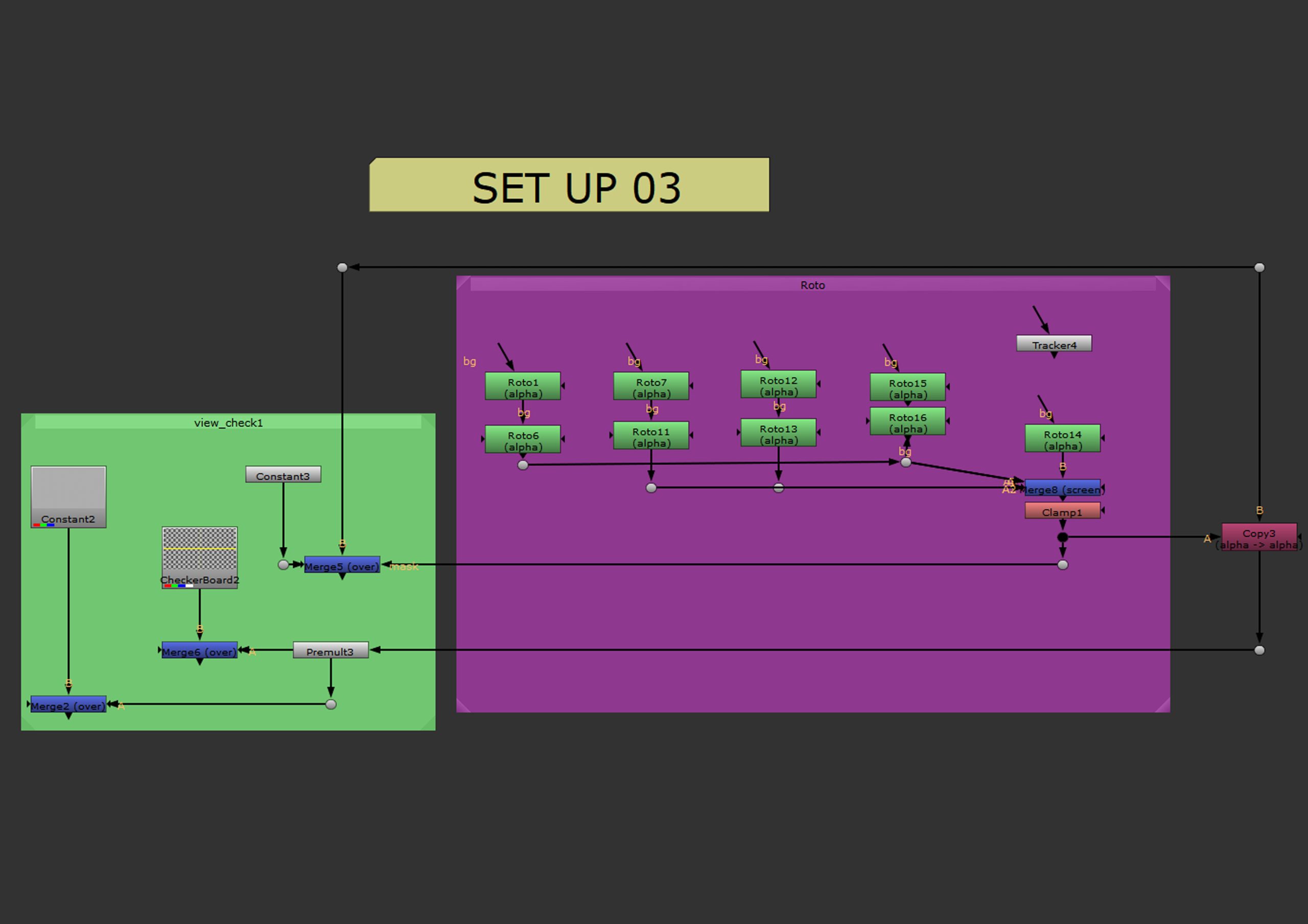
Graph examples of the possible setups as well as some useful graphs for checking the correctness of a roto. Please click to enlarge.

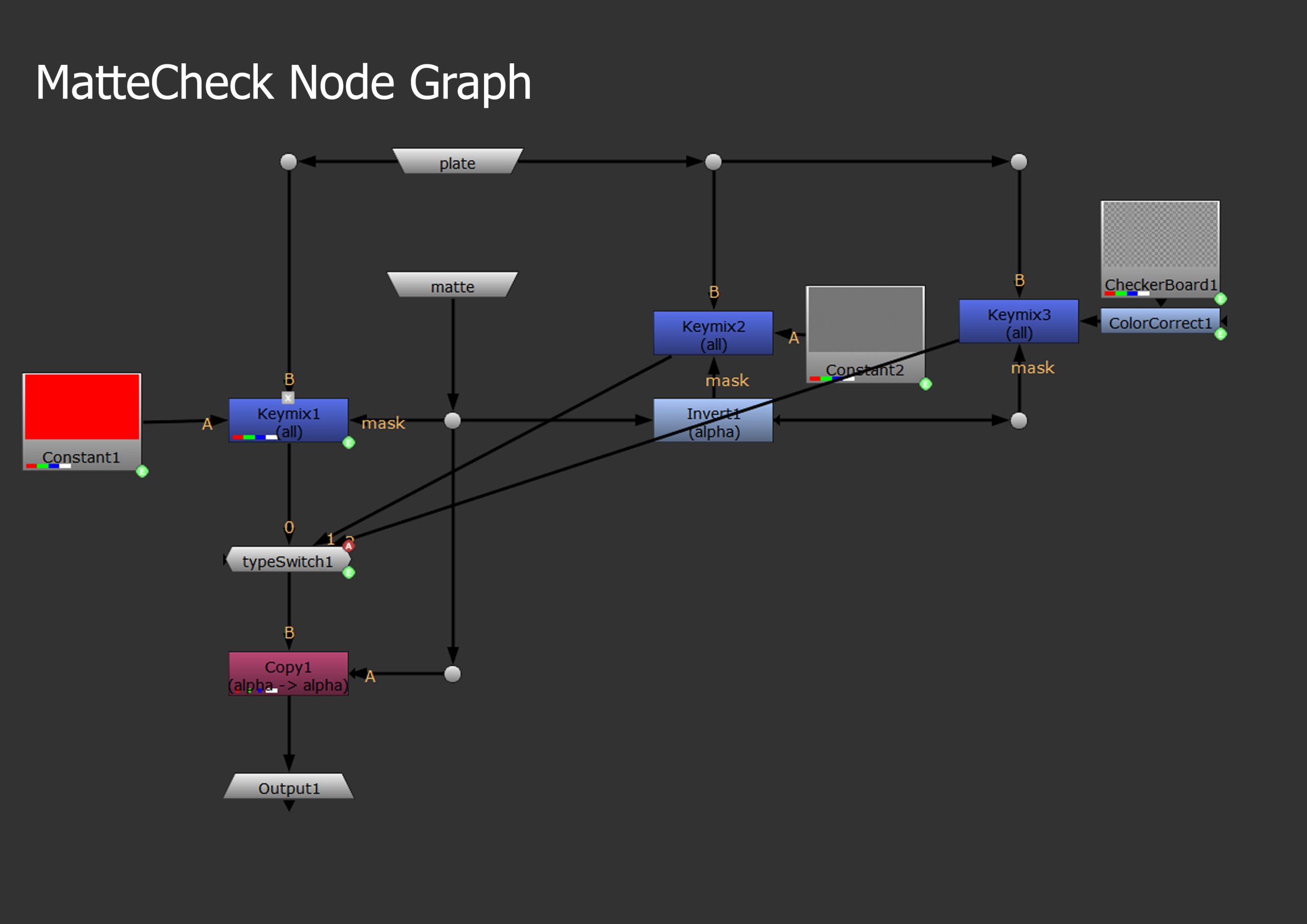
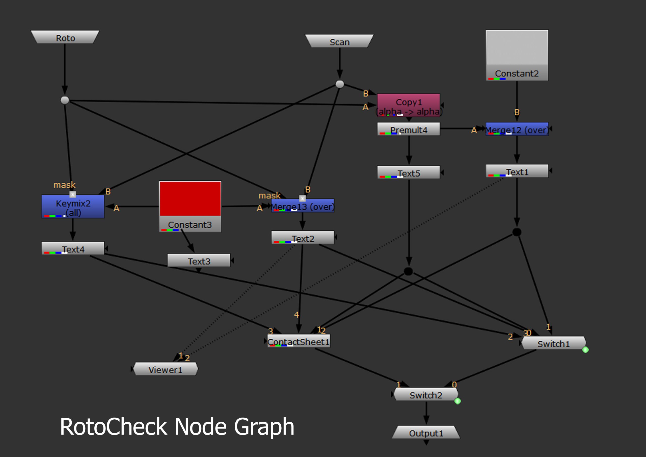
Set up one contains of some roto nodes accompanied by some roto improving tools (blur etc.) and a couple of check graphs. One checking the mat and the other, the workings of the roto (RotoCheck and MtteCheck node graphs below in the following gallery).
Set up two concentrates on the merging of more than one roto together in the form of Merge nodes. It also applies blur and filter in the end to the whole roto (merged elements) and also contains the MatteCheck node graphs.
Set up three also connects multiple rotos into one alpha, but this one explains the importance of a clamp node (or using only multiply screen or union) which ensures that the multiplied alpha value does not go over one in the overlapping areas as is the case with some multiply nodes.
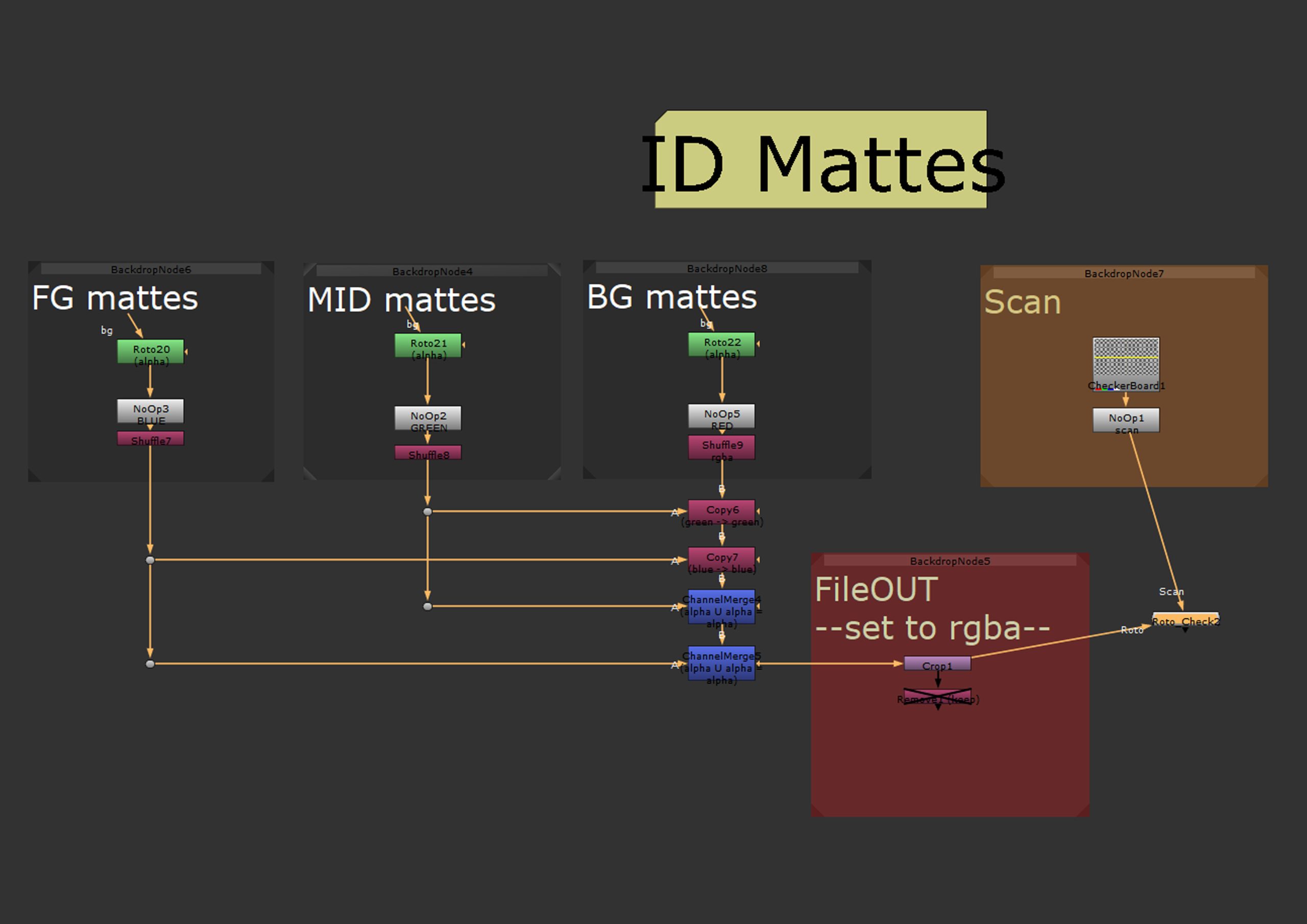
This set up shows the set up for working with multiple RGB mattes, and allows the view of only one colour at the time when selected in settings. Also contains a roto check.
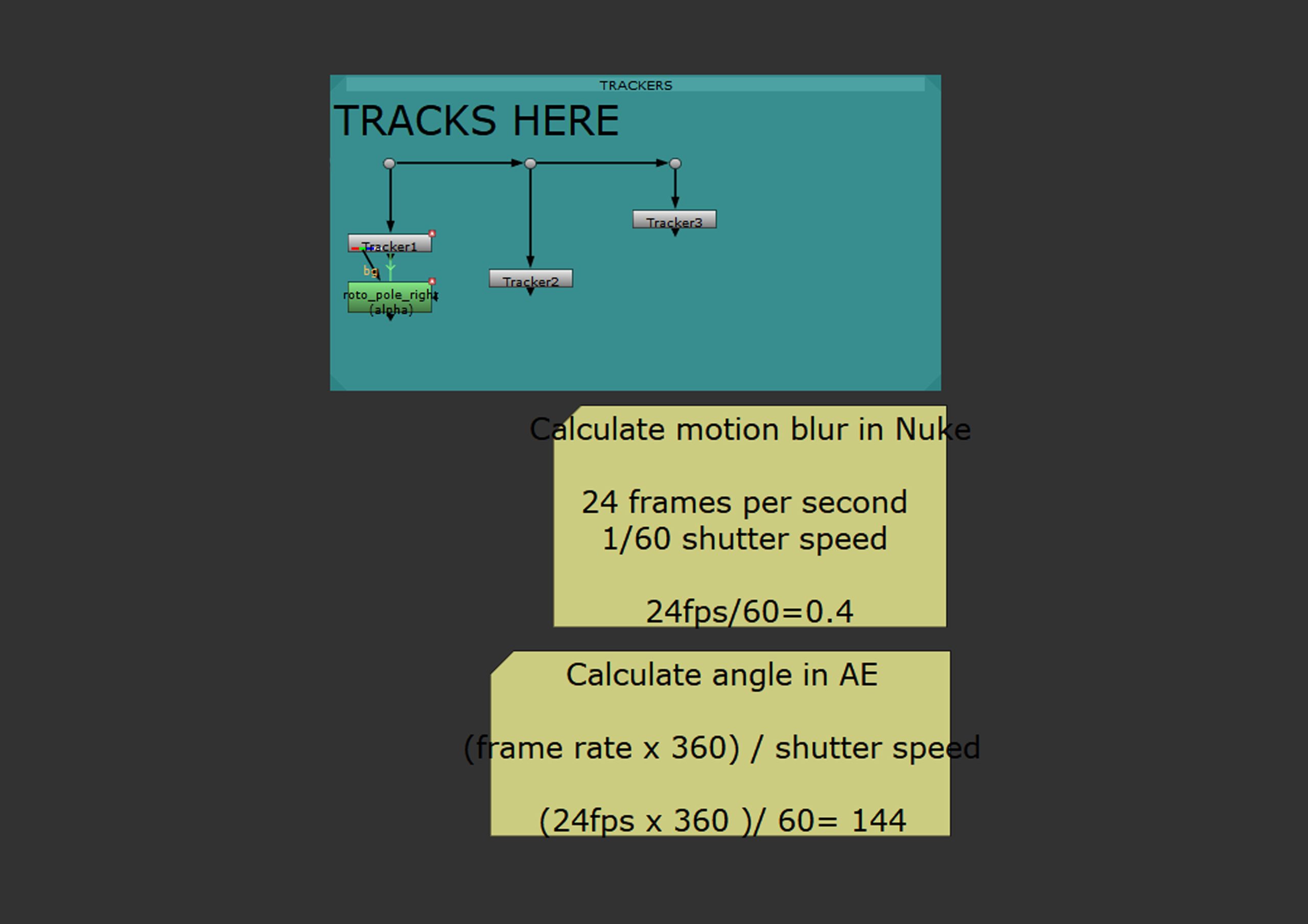
A general set up for tracking. Contains a note on how to calculate the correct motion blur value.
MatteCheck node Graph, shows the structure of the graph used to check the correctness of the matte.
RotoCheck node graph splits the view in four ways. Allowing detailed feedback of the workings of a roto and allows to spot mistakes efficiently.
Progress
A few short videos showing the stages of the roto I have worked on for this weeks exercise.
A short video showing the roto of the head in motion.
The roto with only the alpha visible, in motion.
A video of the tracked point on the pole, needed for further part of rotoscoping the pole out.
Rotoscoped pole, using one track point and a roto with transform properties copied from the tracker.
Week 7
Alpha and Colour Correction
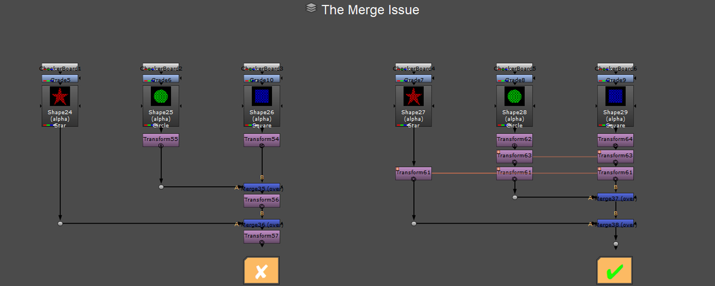
Merging operations
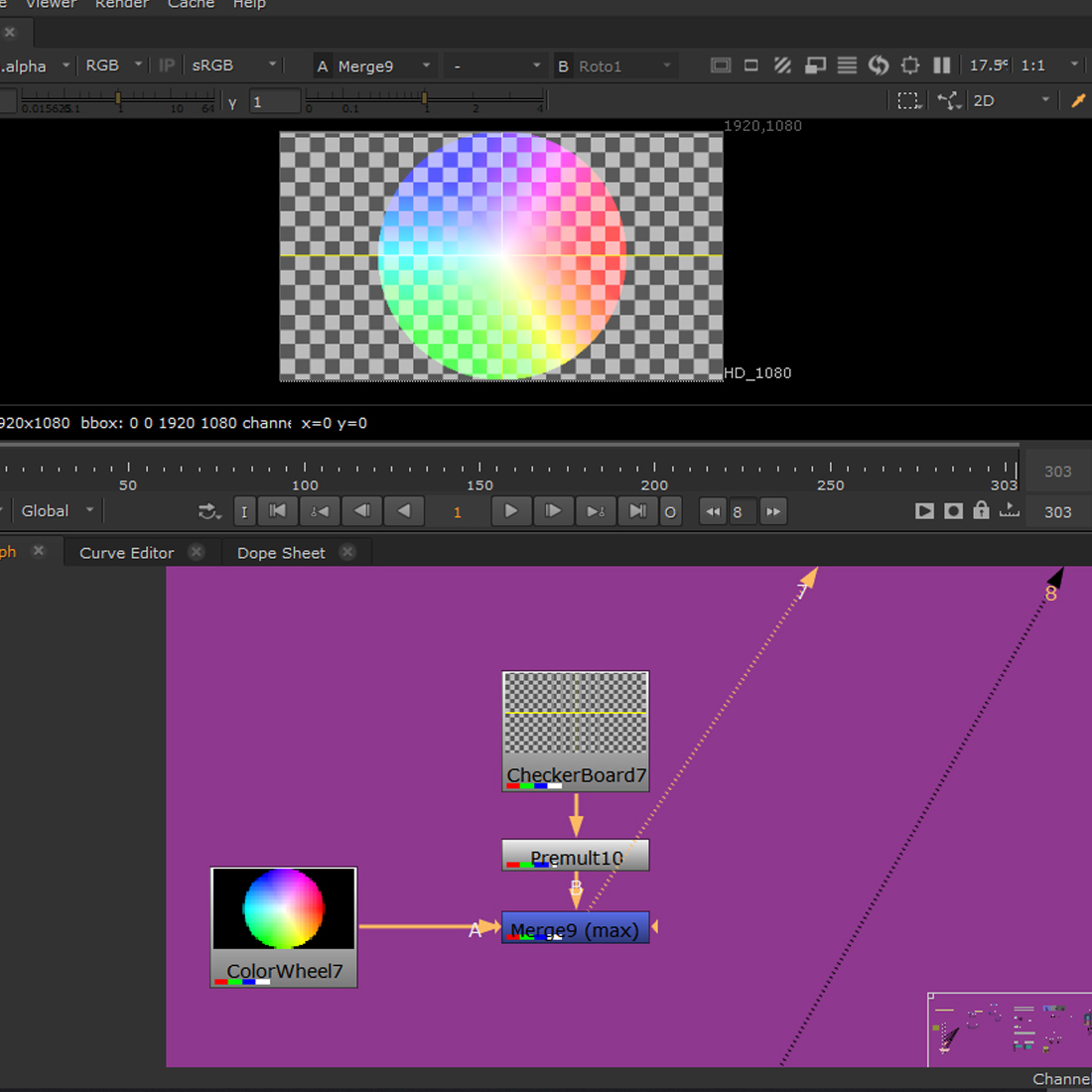
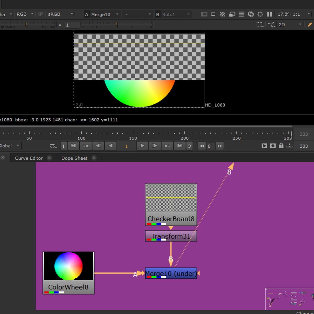
The following screenshots show the different effects of particular blending effects of the merge node (another similar node used is a keymix, which allows unpremult nodes).
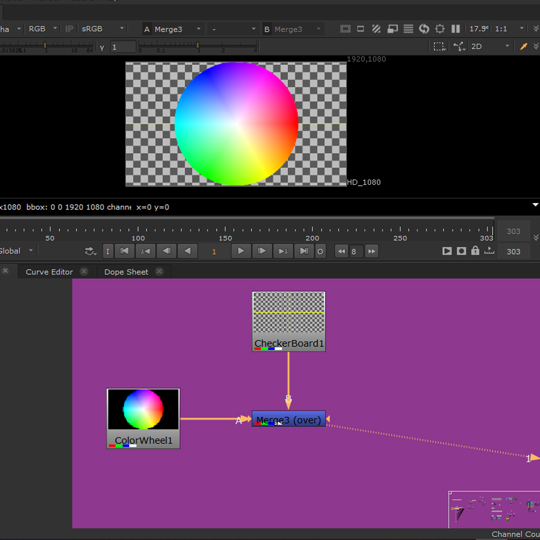
The ‘over’ option allows to display the image (with corresponding alpha – no black) over another one.
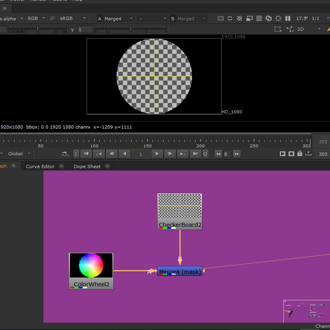
The ‘mask’ option allows to use the alpha assigned to one image to affect another one.
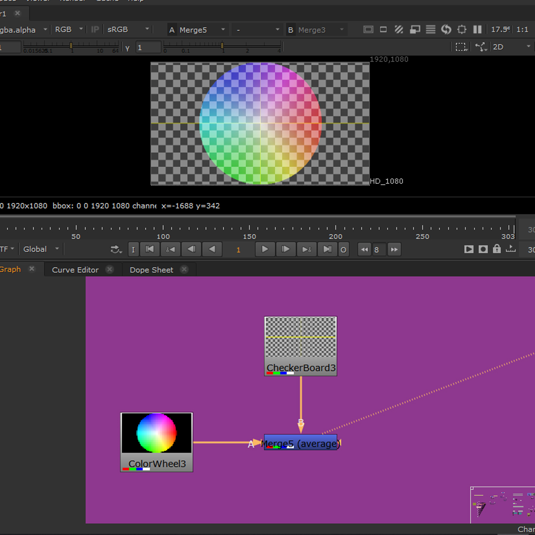
The ‘average’ option uses half the opacity of both images to create one.
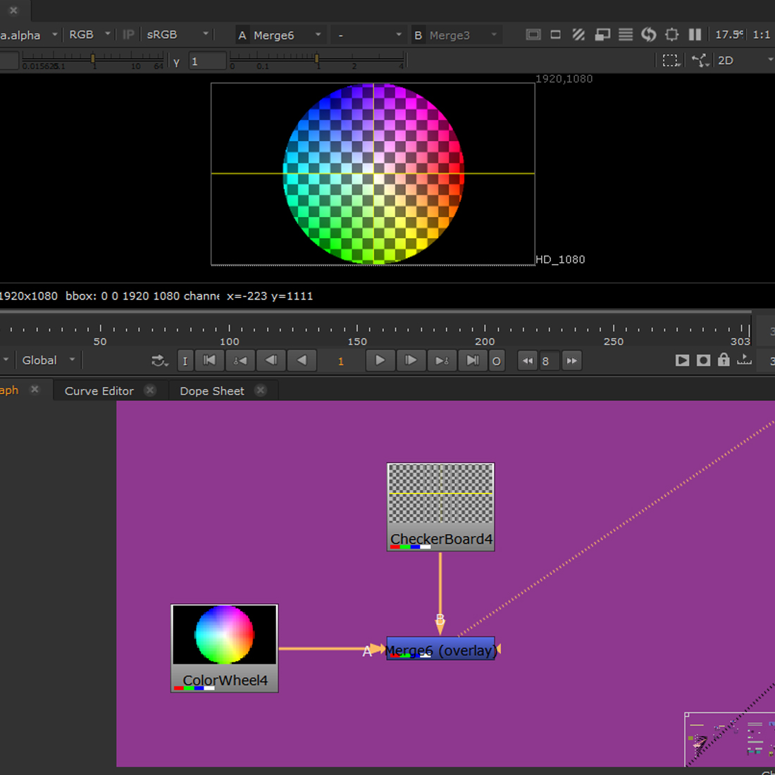
The ‘overlay’ option blends the two images without using opacity, both are affecting each other, keeping their individual properties and slightly increasing them (like overlay in psd? ).
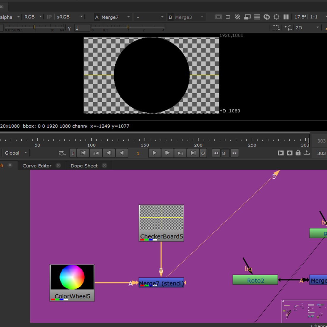
The ‘stencil’ option cuts out the alpha of the image affected, useful for creating custom masks.
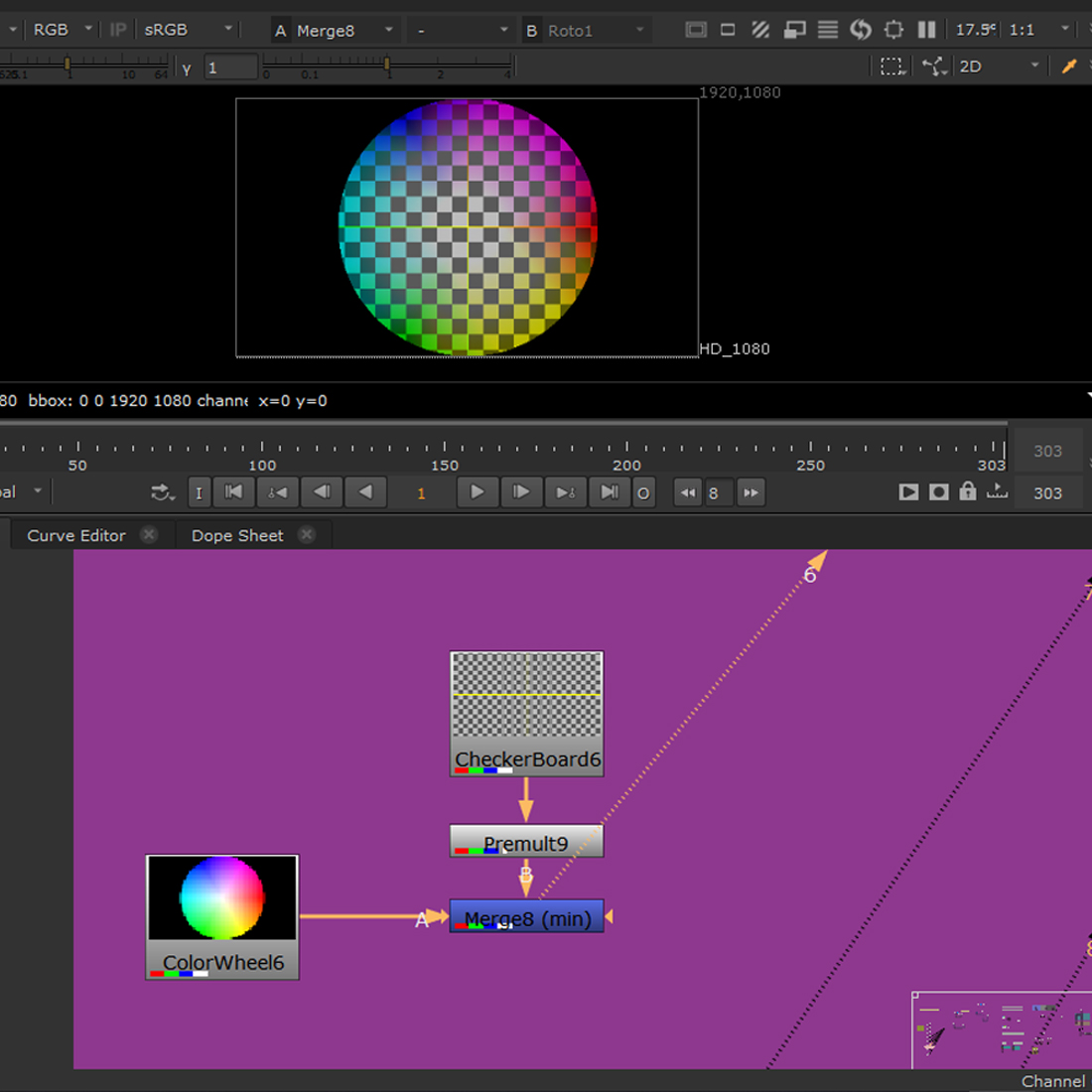
The ‘min’ option, like overlay, blends both of the images affected, but here without changing their properties.
The ‘max’ option blends the images in ‘screen’ like fashion (?), lightning them slightly.
The ‘under’ option places one image under another, without a blending effect (on the picture the checker pattern moved up to show the effect).
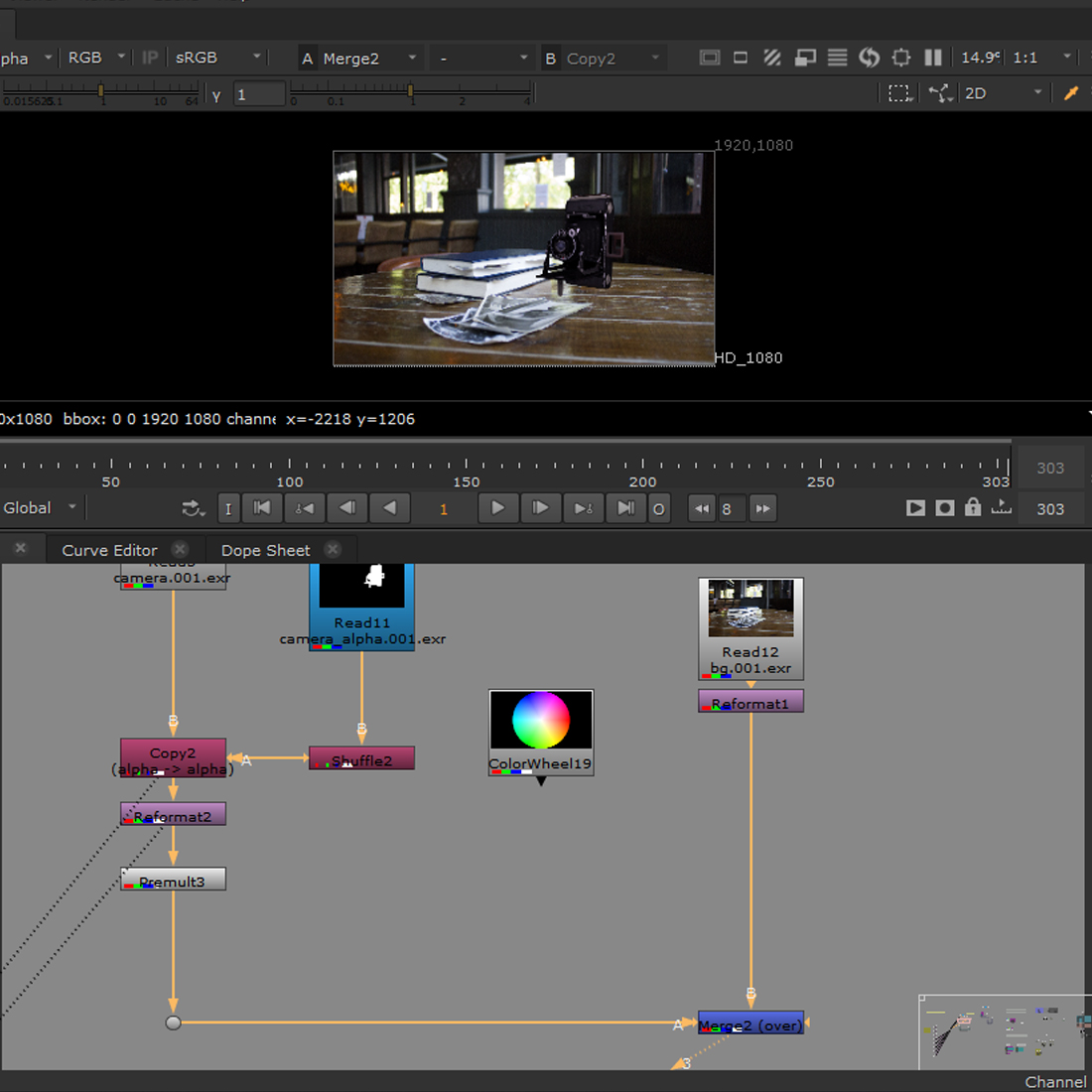
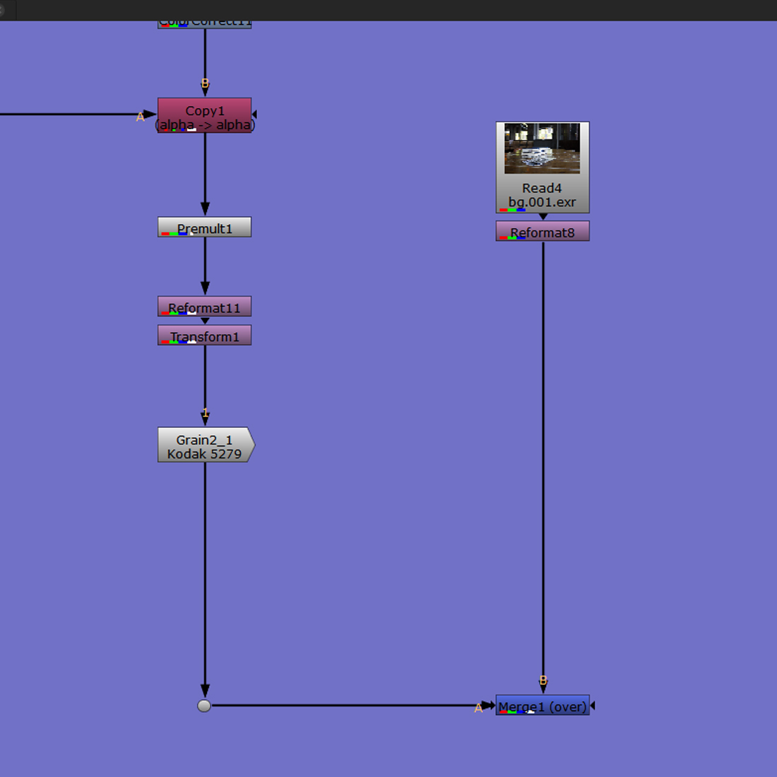
Merge and Reformat
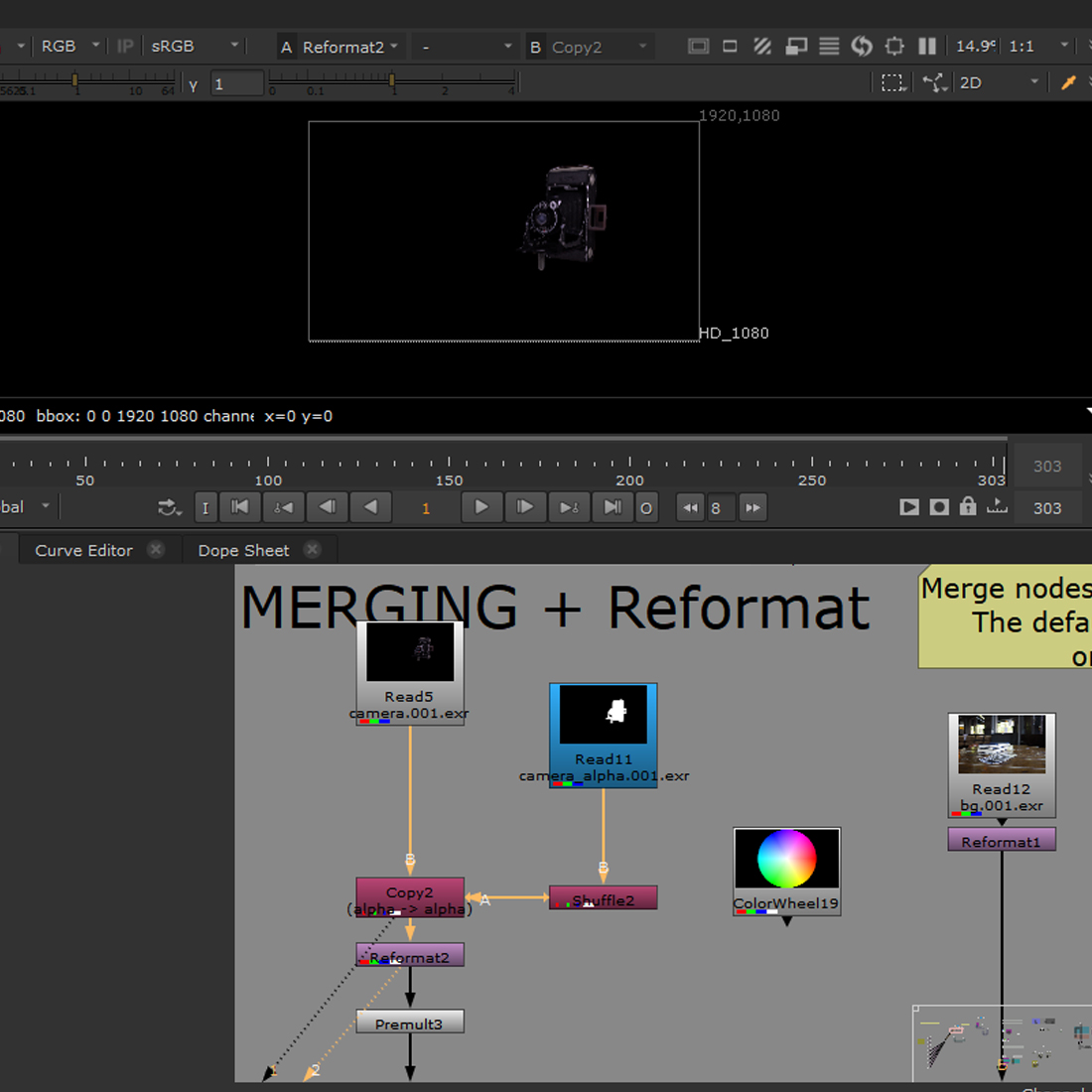
The ability to change the format and colour of a file to match it with another one is crucial to ensure the best match possible.
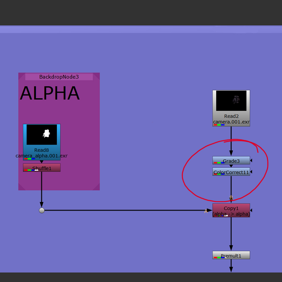
Left: Reformatting two files and merging an image with a corresponding alpha (in case an image had none in the first place).
Right: Applying the two files (image and alpha) over a new background with some tiny colour corrections (multiply, over node).
Premultiplication
By default the premult node multiplies the RGB of the input by its alpha (pemultiplies the input image).
Used to specify the area of the alpha effect.
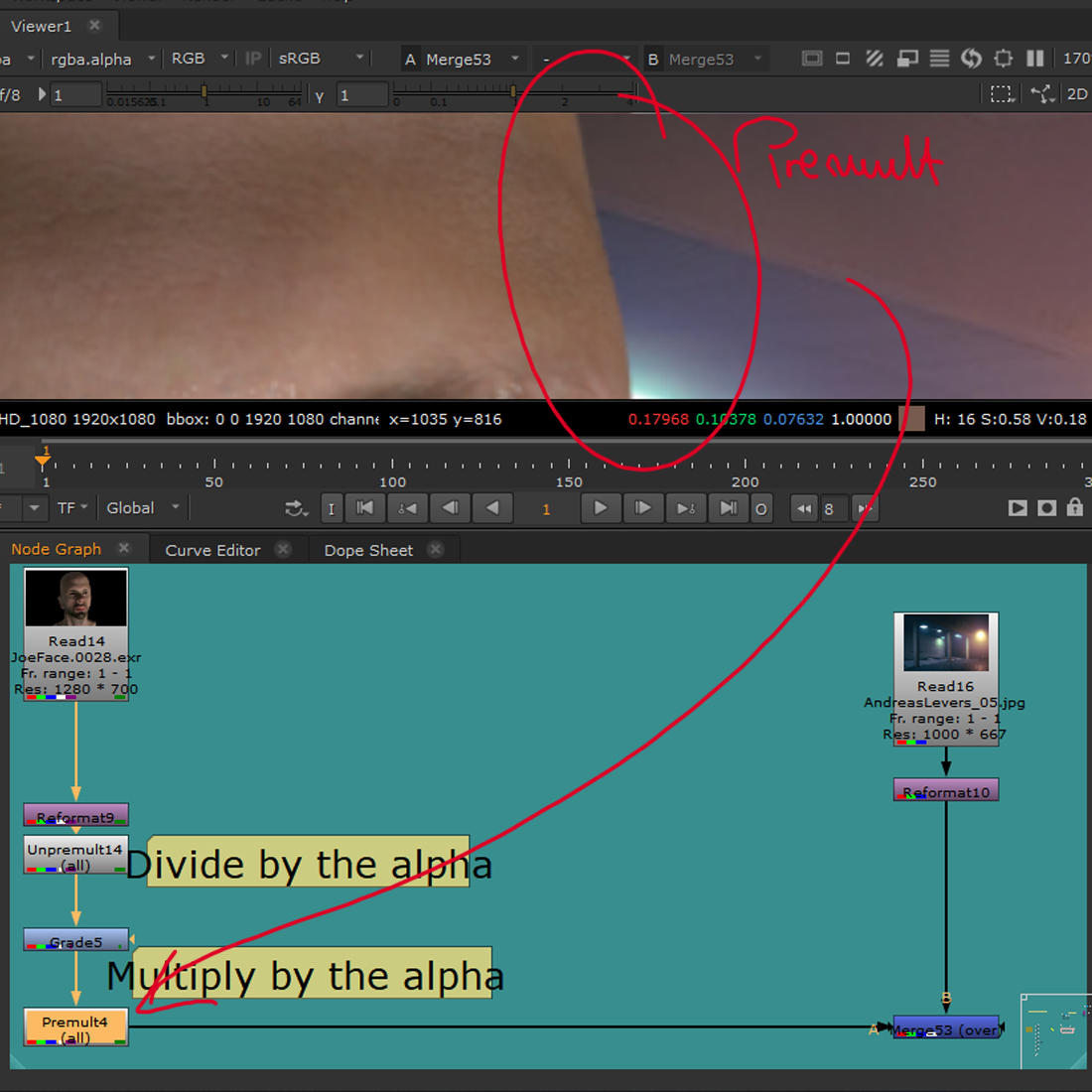
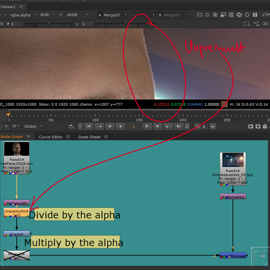
When an image, premultiplied beforehand (or CG) is merged with another one without the unpremult node, the black part of the alpha keeps the value it had and will be treated as such instead of an empty space (that we want) and so, every colour correction will affect the background in wrong way (as it affects the transparent black on top of the actual background, instead of ignoring that area).
When an image that has ben premultiplied once, is affected and premultiplied again (without unpremult node before the node that affects the image like grade, exposure etc.) it will loose much of the semi-transparent areas to a darkened halo around the subject
Colour space and Linearization
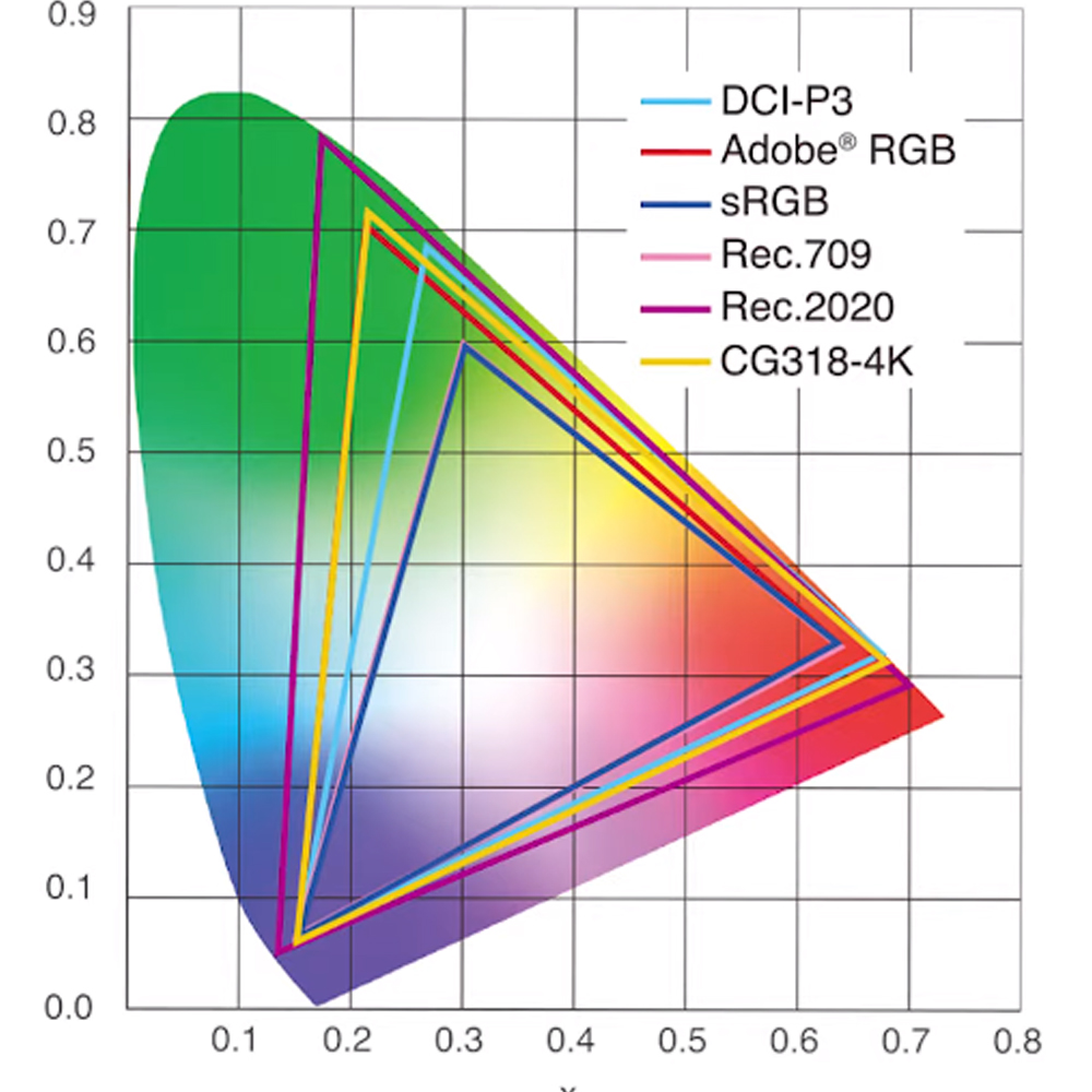
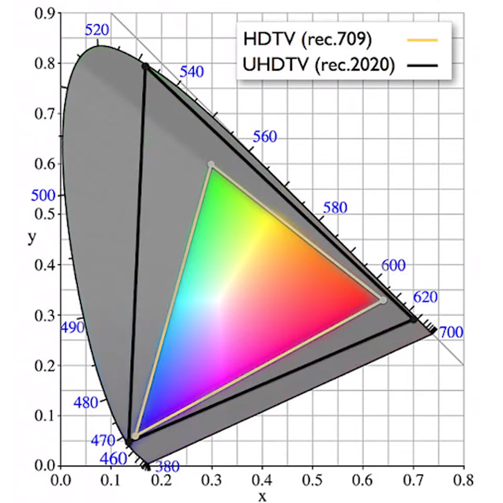
Colour space is a way to describe capabilities of a particular device or file, they allow a glimpse into understanding how the file will behave in another devise or setting, pointing to how much the file may be compromised when used in a different colour space, how much of the highlight, shadow, saturation etc., will be retained or lost. It is an identifier of how the colours will be interpreted, while reading around a particular white point.
Colour space points towards the way a file was captured and exported and defines further steps that are needed before the usual post workflow can be employed. One colour space device captures a particular spectrum of colours, and when it is displayed on a device that employs a different colour space, some of the values of the original can be outside of that colour spectrum, Meaning that the colours are still there but we see them differently, as that new device doesn’t have the capability to show us the actual values (outside that device colour spectrum). The file can however be converted to match the new space and display the right aesthetic (although the colour values will be different to the original, to ensure that the new device can handle and display them correctly).
Colour spaces also heavily rely on a gamma value identifiers, which is the way a device handles the luminescence, allowing for highlight/shadow extractions.
https://www.studiobinder.com/blog/what-is-color-space-definition/
Most files are non-linear, which means they need to be linearized (process converting files into linear space) as Nuke tools are created based on a linear match.
LUTs, CDLs and Grades


Colour grading is the process of treating the whole piece to a colour adjustement in terms of achieving a desired effect through a particular look and tint (colour connotations), like evoking an emotion in the viewer. Some movies have a constant colour pallet while other ones change the grade depending on a shot.
Colour grading changes the general look of a file to suit an artistic and stylistic requirement (convey emotion, time of a day, location etc.). LUTs (Lookup tables) are numerical pre-sets, providing a shortcut for a particular colour adjustment (transforms colour input values), meant to achieve a particular stylistic effect.
CDLs (Colour Decision List) are also used to a similar effect, however they are significantly less stylized and less destructive.
https://www.studiobinder.com/blog/what-is-lut/
https://www.studiobinder.com/blog/how-to-use-color-in-film-50-examples-of-movie-color-palettes/
Colour Correction
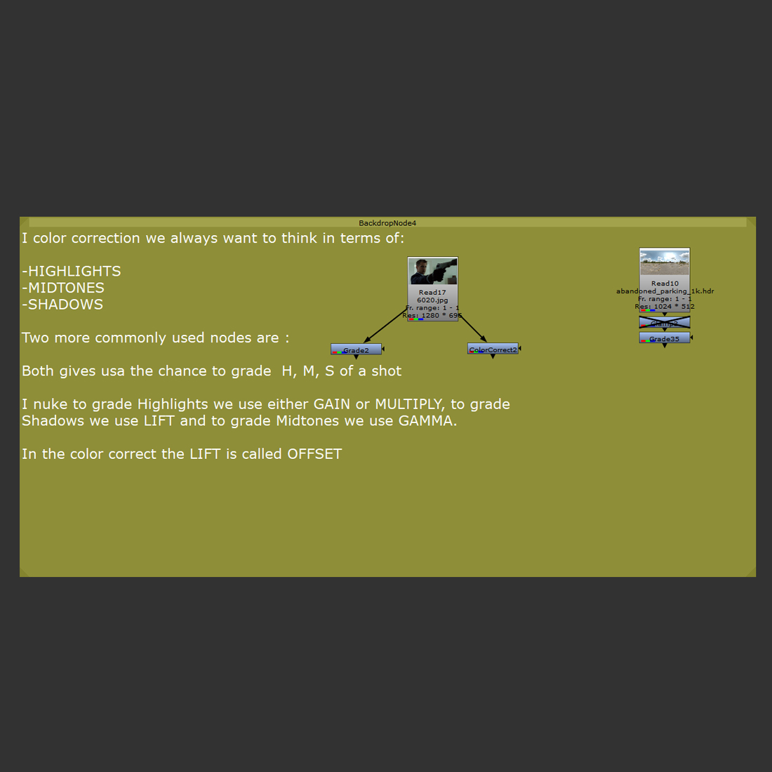
Colour correction is the process of correcting the individual parameters of a footage as opposed to colour grading, in which many shots are manipulated to match the same feel.
Very basic and simple colour correction workflow set up and hierarchy.
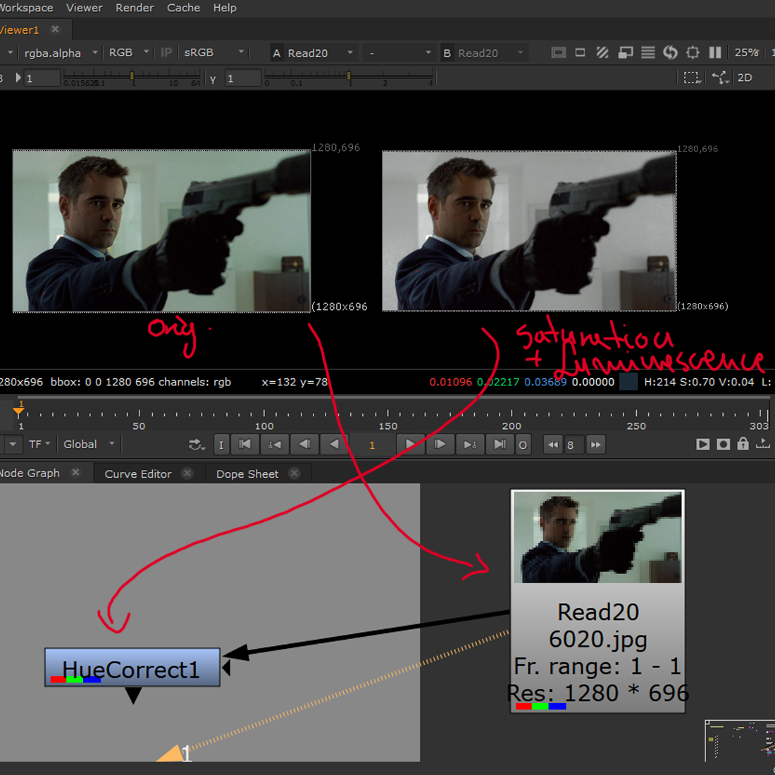
Three examples of the actual effect the nodes and settings used, have on the image.
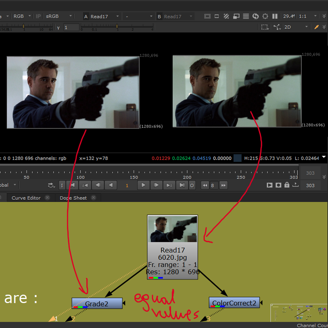
Histogram – Equal values of RGB.
Hue Correct node – Saturation and luminescence adjustments.
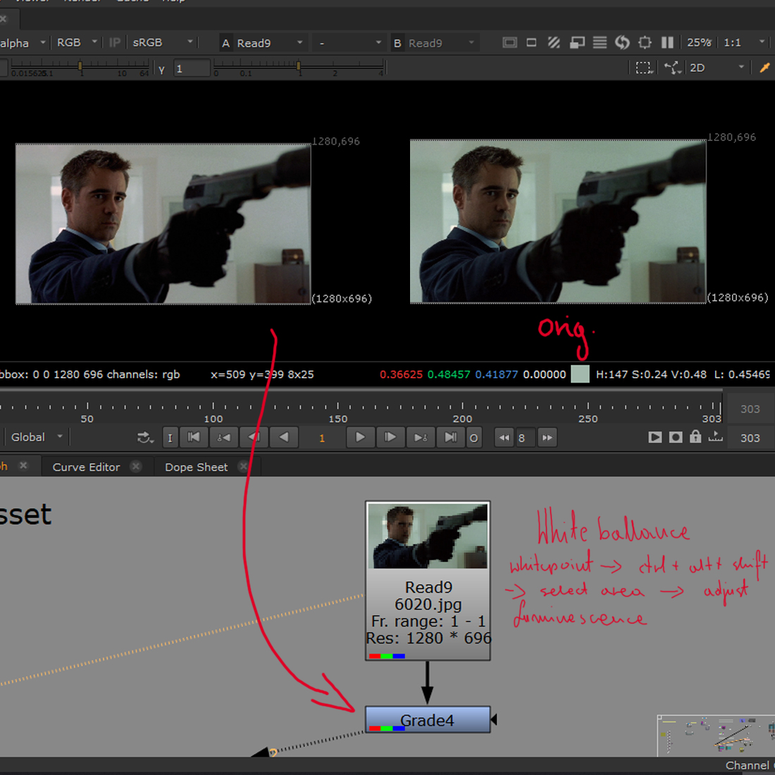
Grade (whitepoint) – White balance.
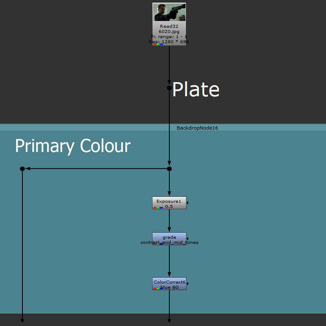
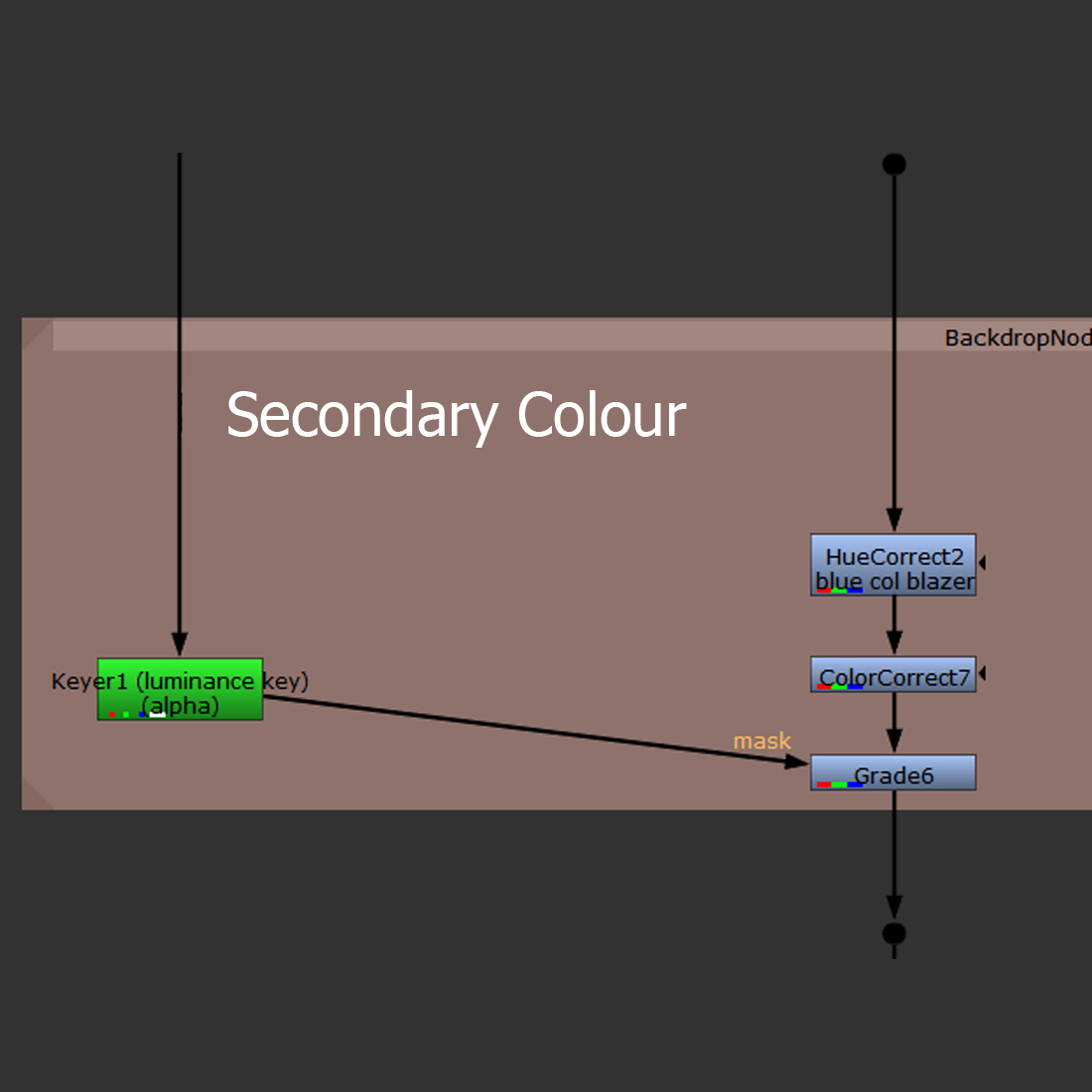
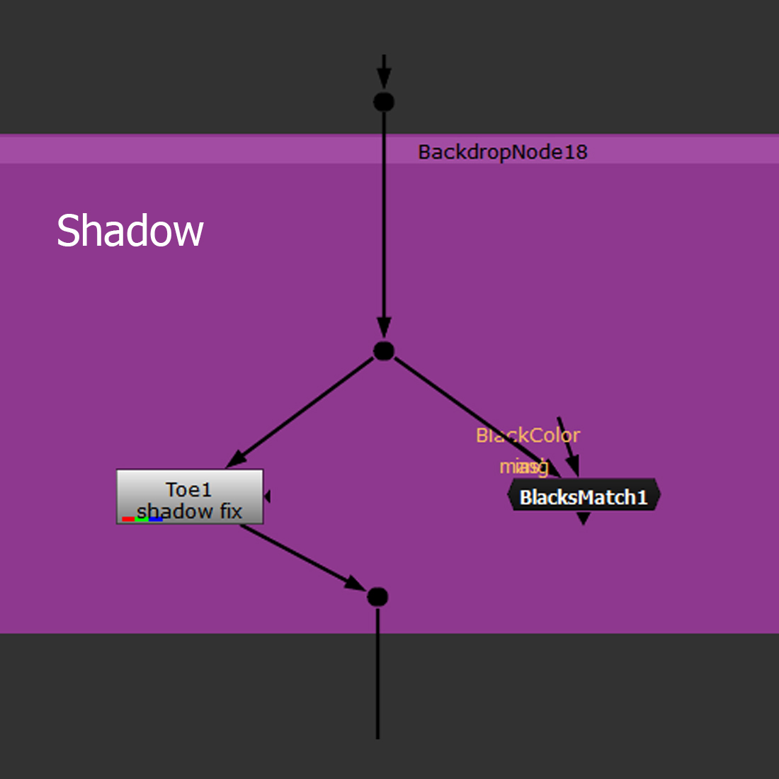
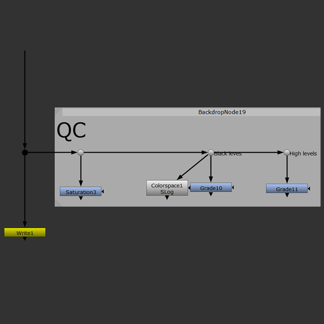
A very simple and basic colour grading hierarchy and order in which the operations should be done.
Exercise

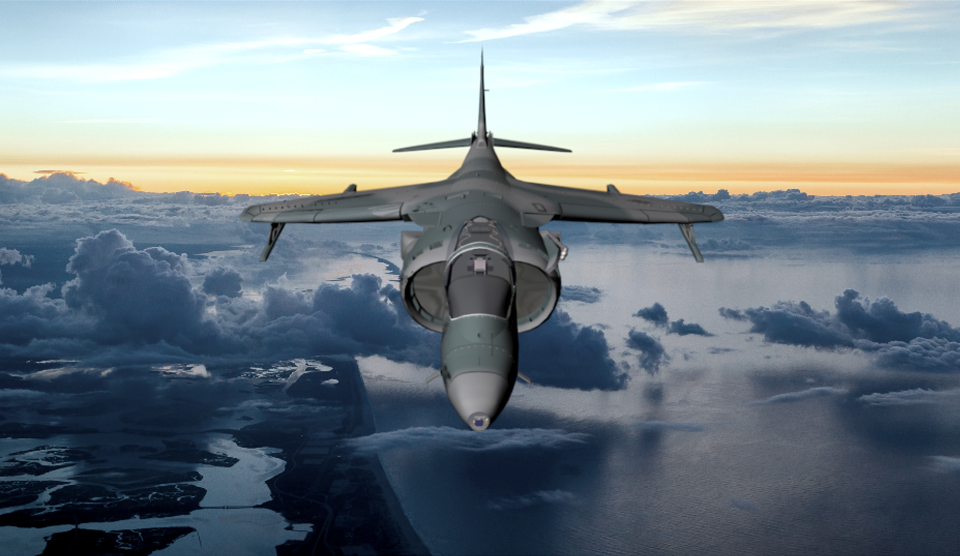
The original file.
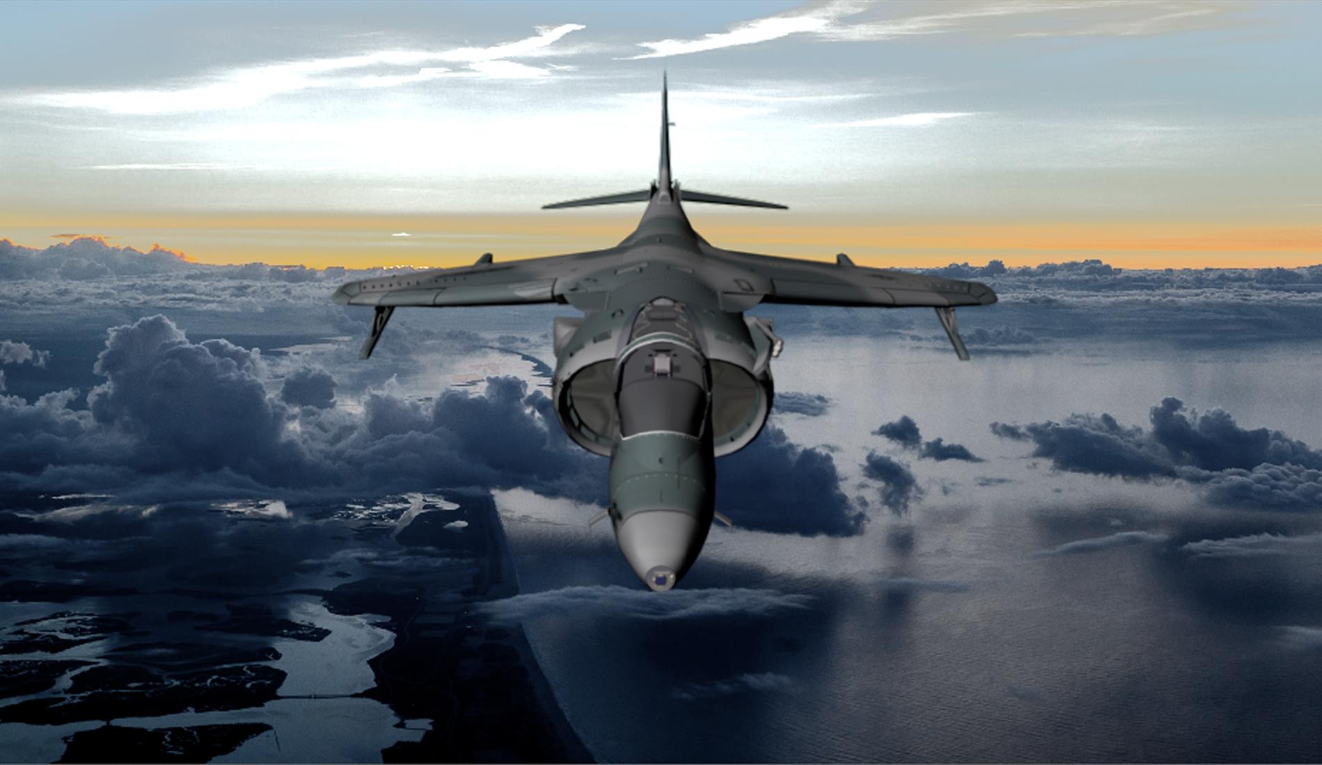
Colour corrected file.
Colour grading experiment.
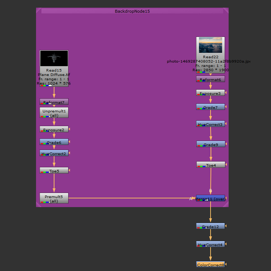
The hierarchy of the actions taken in the exercise as well as a time-lapse of the process.
Week 8
Tracking I – stabilization and screen replacement
Tracking is a process that allows the extraction and storage of data from the footage. It can be then applied to other elements to match their transformation relative to the camera as well as back to the footage it was extracted from, in terms of stabilizing the image.
Tracking
Tracking requires placing tracking points in the footage, to allow the algorithm to analyse their position and movement, in terms of later using that data in further operations and adjustments. Crucial for replacing or adding stuff, it ensures a match between the movement of those elements and the one from the camera as well as parallax considerations.
Stabilization
Stabilization is one of the techniques employed in improving the quality of moving picture work. It uses algorithms and equations to digitally manipulate the file in order to clean up a footage movement and make sure it doesn’t jump around the screen, decreasing the engagement factor (confusing and distracting the viewer).
In nuke it uses a single tracking point, placed near the area that is supposed to be the central point of the movement and stabilizes the movement around that point by using an algorithm, contained within a ‘transform – stabilize’ node.
Screen replacement – corner pin
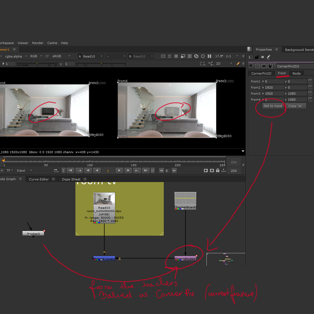
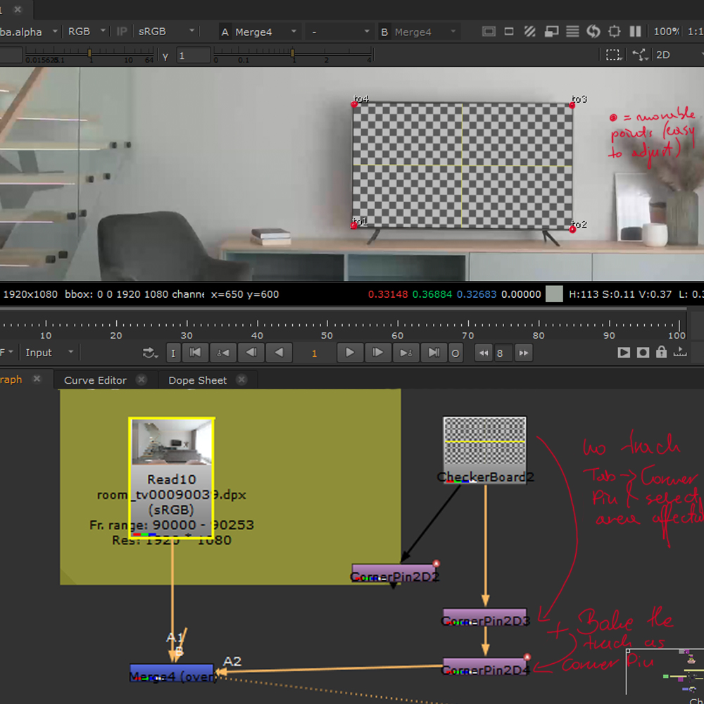
Corner pin is a node or expression that allows an easy screen replacement. It requires tracking information fed to a corner pin node in order to replace the required region with the new image (specified by corner pin tracking or the adjustment of a corner pin node) and ensure a seamless follow of the track by the new image.
Exercise
Screen replacements are a very common part of VFX, they require tracking, image manipulation and sometimes rotoscoping. In this exercise we had replaced green screen with the still image (track and Corner Pin) and roto out the fingers so we could place them on top of the image to make this comp work.
Week 9
Tracking II – filtering
Image filtering allows the manipulation of file to achieve a desired effect. Filters help to define what happens in the picture values of an image while performing operations in which we transform and process the files.
Concatenation
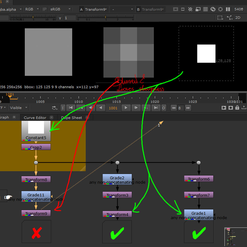
Concatenation means the joined effort of multiple filters from one family. In practice it means less processing time and footage degradation as the right order of actions can ensure filtering the least amount of times.
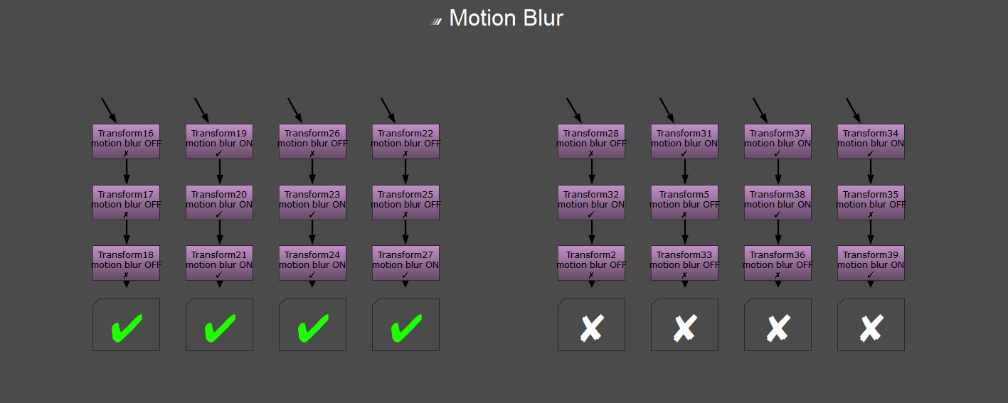
The image on the left visualizes that idea – the first group on the right filters the image three times ( 1x transform +1x grade + 1x transform = 3 filters and 3 x filtering) instead two times like the middle and right one are doing (2x transform + 1x grade – and inverted – both equal 3 filter nodes but only 2x performing the filtering) as the same family nodes do their maths together, instead separately.
Conclusion: group the nodes according to the family they come from, to ensure efficient workflow and minimum render time.
A broken chain of concatenation (i.e., inserting a grade between two transform nodes) will result in loss of quality and blurred images.
Note: the filter and motion blur of all the concatenating nodes would be set by the bottom-most node (the last one) and if all the previous node had the motion blur on but that last one didn’t, then there would be no motion blur in the final outcome of the comp.
http://www.nukepedia.com/written-tutorials/concatenation-of-transforms-in-nuke
Bounding Box (BBOX)
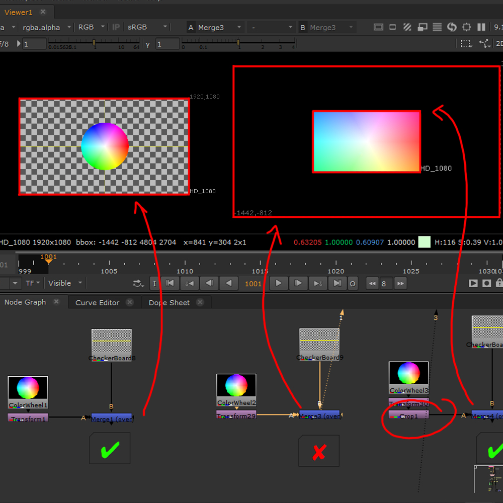
Bounding Box is the area of the comp that is affected by the algorithms of the actions performed. When scaling up elements, the BBOX is scaled up as well, and by default it stays the same as the largest element of the composition, increasing the are (not visible on the screen in the end) that needs to be calculated and essentially rendered, decreasing the efficiency and time consideration of the process (can slow down the software). To avoid that, a simple crop or change of the setting (merge node -> set bbox to -> intersection) can be used.
Shuffle node
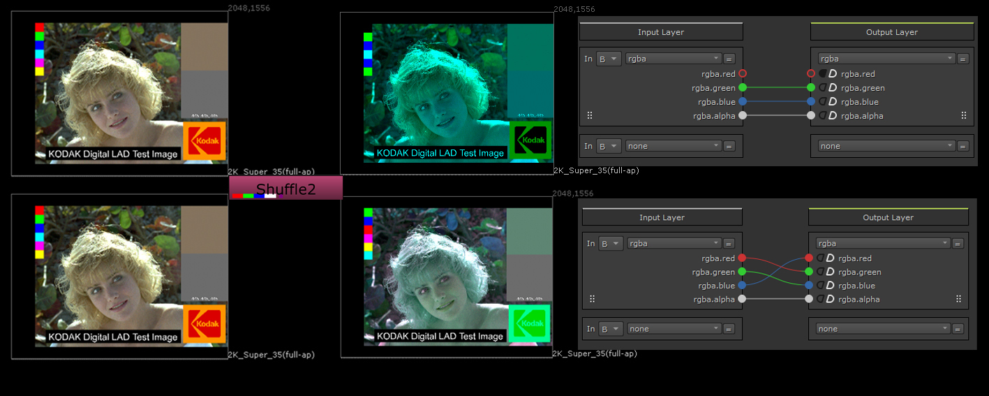
Shuffle node, connected only to B allows to make easy and quick changes in channels, allowing colour channel adjustement and changing between the channel output one wants to work with. Depending on the settings chosen, different elements of the file can be separated out and further adjusted.
Blur, Defocus and Convolve
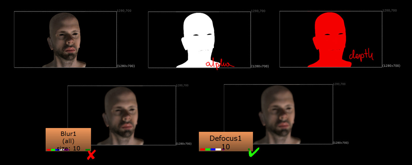
Blur is one of the most commonly used filters, but in most cases using a defocus can give much better and natural looking results, it is however a much heavier node.
The first picture on the left, displays the general differences between the two. Blur looks more stylized and unrealistic, while the softer, but stronger defocus bring up much more organic and not so perfect result, making it appear more believable.
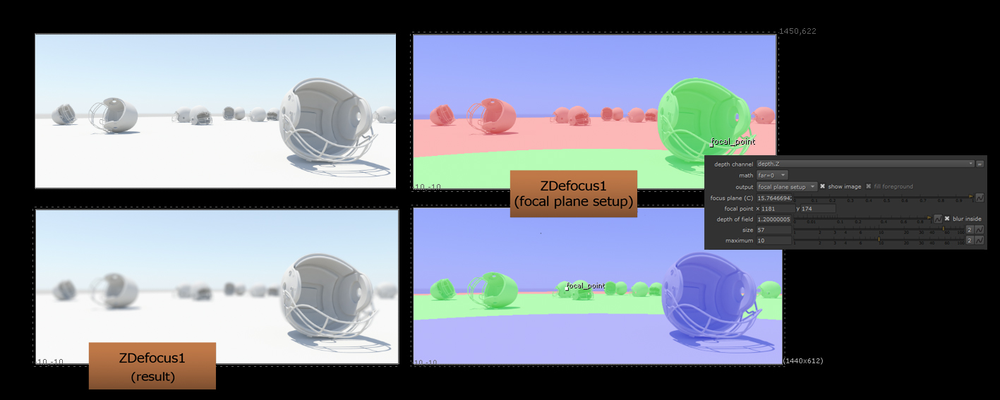
The next picture concentrates on working with the ZDefocus node, which gives full control of how the node affects the file. All aspects of the defocus can be adjusted to ones liking and it brings very realistic effects.
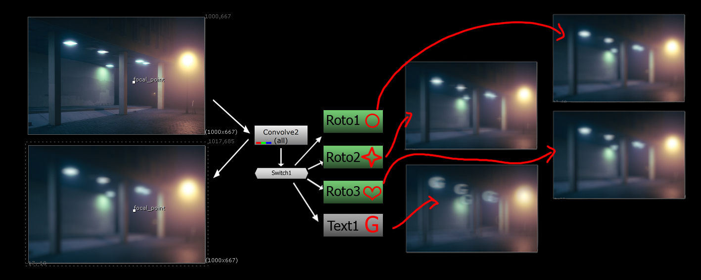
The last picture shows the possibilities of working with Convolve, it allows, through the use of a shift node (and specifying the input shape directory from the arrows connected) to plug different shapes from which the blur will borrow its final form and direction.
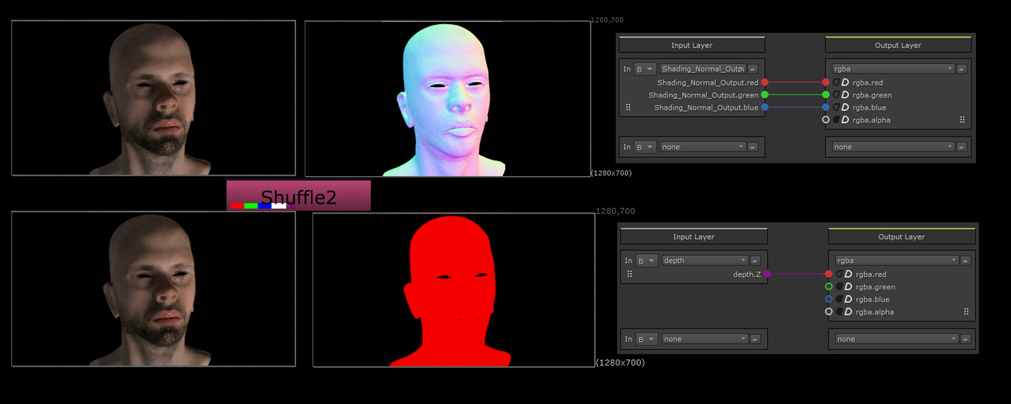
Depth
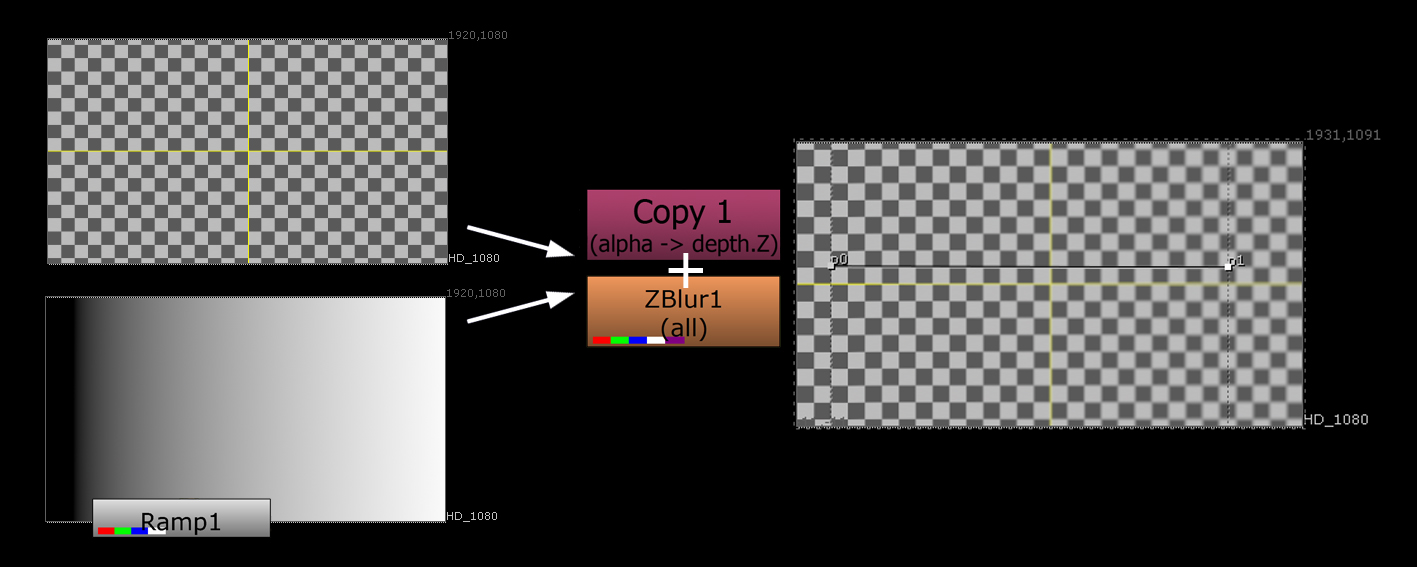
Every node that works in a similar fashion as blur or defocus need a depth channel to specify the way and direction of the effect. It is essential with Defocus, as without the specification of foreground and background the focus shift visible on the second picture in the previous section would not be possible.
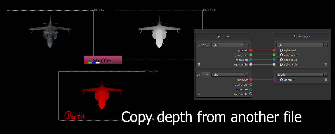
This is done by the depth channel, often included in the CG elements but also easily improvised in nuke (second picture on the left). Depth can also come in a separate file, which needs to be attached to the diffuse by a shuffle node which allows linking two elements of the same file together and specifying the way those elements are meant to be read.